MAINTENANCE
troubleshooting
and repair
The four groups (denoted by the A’s, B’s,
Cs and D’s) in the seif-test report correspond to
different test categories. These
tests
are described below, including a tabulation of the
Generator instrument state and the
test codes that result if any test fails to achieve the
expected result. Understanding
how these tests are done can provide more
meaning
to the
results and can assist in understanding how they relate
to
other symptoms. A successful
self test is reported with all zeros.
During
the
self
test,
the step attenuator is programmed to
maximum
attenuation and the
internal frequency reference is selected. The
analog circuit tests make use of the unleveled
(UNLVL)
and unlocked (UNLOK) status detectors,
whereas
the digital circuit tests make
use of write/read techniques.
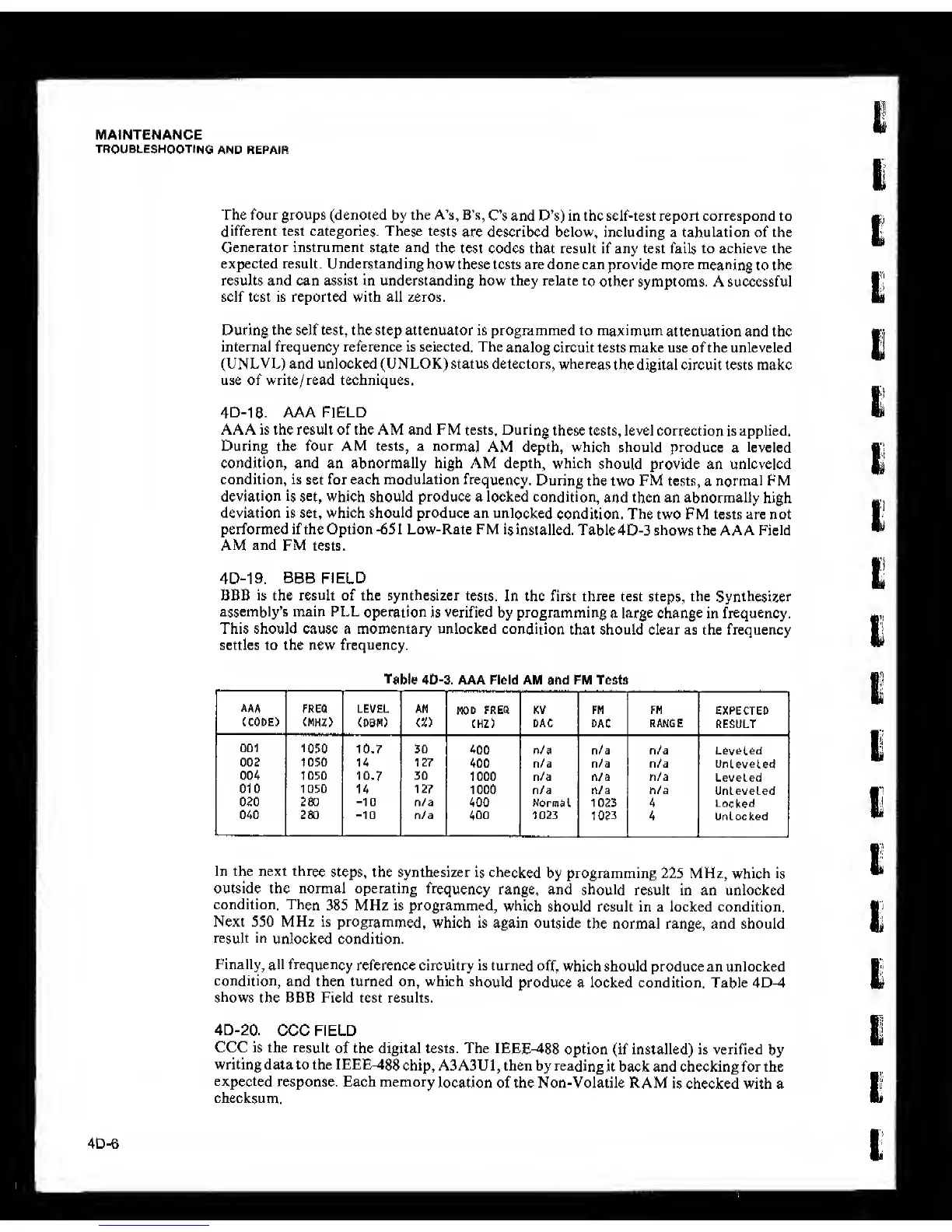
4D-18. AAA FIELD
AAA is the result of the AM and FM tests. During
these tests, level correction is applied.
During the four AM tests, a
normal
AM depth, which should produce
a
leveled
condition, and
an abnormally high AM depth, which
should
provide an unlcveled
condition, is set for each modulation
frequency.
During the two FM tests,
a
normal FM
deviation is set, which should produce
a
locked
condition,
and then an abnormally high
deviation
is set, which
should produce
an unlocked
condition.
The two
FM
tests are not
performed if the Option
-^5
1 Low-Rate FM
is
installed. Table 4D-3 shows the AAA Field
AM and FM tests.
4D-19.
BBB
FIELD
BBB is the result of the synthesizer
tests.
In the first three test
steps,
the
Synthesizer
assembly’s main PLL
operation is verified by programming
a large change in frequency.
This should cause a momentary unlocked condition
that should clear as the frequency
settles to the new frequency.
Table 40-3.
AAA Field AM and FM Tests
AAA
(CODE)
1
LEVEL
(DBH)
,
AM
(X)
MOD
FREO
CHZ)
KV
DAC
FM
DAC
FM
RANGE
EXPECTED
RESULT
001
1050
10.7
;
30
1
400
n/a n/a n/a Lovolad
1050
!
u
'
127 1
400 n/a n/a n/a
unleveled
BiLH
1050 10.7 30
1000 n/a n/a n/a
Leveled
010
'
1050
U
127
1000 n/a n/a n/a
Unleveled
280
-10
n/a
400 Normal 1023 4
Locked
280
-10
n/a 400 1023
1023
4 Unlocked
In the next three
steps, the synthesizer
is checked
by programming
225
MHz,
which is
outside the normal operating
frequency
range, and
should
result in an unlocked
condition.
Then
385 MHz is programmed,
which
should result in a locked condition.
Next 550 MHz is
programmed,
which is again outside
the normal range, and should
result
in
unlocked condition.
Finally, all frequency
reference circuitry is turned
off, which should produce an unlocked
condition,
and then turned on, which
should
produce a locked condition. Table 4D-4
shows
the BBB Field test results.
4D-20.
CCC FIELD
CCC is the
result
of the digital tests. The
IEEE^88
option (if installed) is verified
by
writing data to the IEEE^88
chip, A3A3U
1 ,
then by reading
it back and checking for the
expected
response. Each memory
location of the Non-Volatile RAM
is checked with a
checksum.
4D-6