MAINTENANCE
TROUBLESHOOTING
AND REPAIR
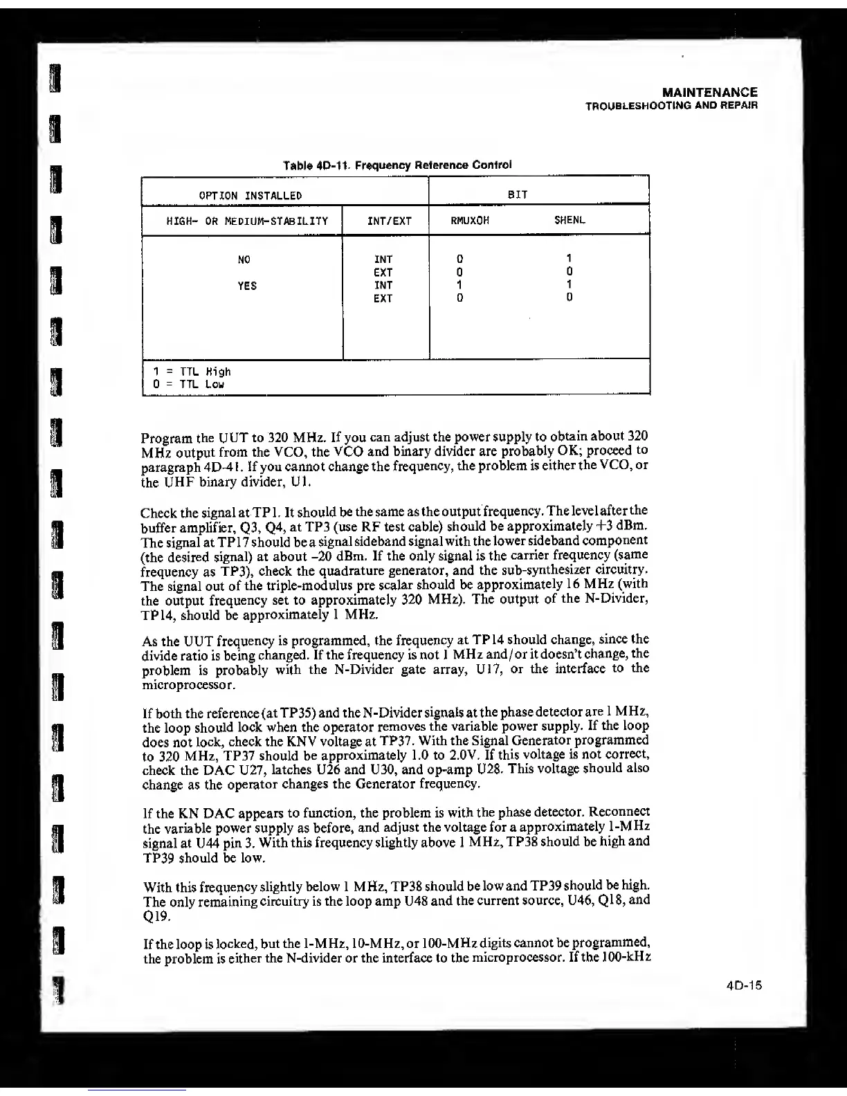
Table 4D-11.
Frequency
Reference
Control
OPTION INSTALLED
BIT
HIGH- OR MEDIUM-STABILITY INT/EXT
RMUXOK
SHENL
NO
INT 0
1
EXT 0
D
YES
INT 1
1
EXT
0 0
1
=
TTL High
0
=
TTL Low
Program
the UUT to 320 MHz, If you
can adjust the power supply to
obtain about 320
MHz
output
from the VCO, the
VCO
and binary divider are
probably
OK; proceed
to
paragraph 4D^
I
,
If you cannot change the
frequency,
the problem is
either
the VCO, or
the
UHF binary divider, UK
Check the
signal at TP 1 . It
should be
the same as the output
frequency
. The level after
the
buffer amplifier,
Q3,
Q4,
at TP3 (use RF lest cable)
should
be approximately T3
dBm.
The
signal at TP17 should be a
signal sideband signal with the
lower sideband
component
(the
desired
signal) at about
-20 dBm. If the only signal is the
carrier frequency
(same
frequency as
TP3), check the
quadrature generator, and the
sub-synthesizer circuitry.
The signal out of
the triple-modulus pre
scalar
should be
approximately
16 MHz
(with
the output
frequency
set to approximately
320
MHz). The output
of
the N-Divider,
TP
14,
should be
approximately 1 MHz.
As the UUT
frequency
is programmed, the frequency
at
TP 14 should change,
since the
divide ratio is being
changed. If the frequency is not I
MHz and/orit doesn’t
change,
the
problem is probably
with
the N-Divider gate array, U17,
or the interface
to the
microprocessor.
If both the reference
(at
TP35) and the N-Divider
signals
at
the phase detector
are 1 MHz,
the loop
should
lock when the operator
removes the variable power
supply.
If the loop
does not
lock,
check the KNV voltage at
TP37. With the Signal
Generator
programmed
to 320
MHz, TP37 should
be
approximately 1.0 to 2.0V. If
this
voltage is not
correct,
check the DAC U27,
latches U26 and U30, and op-amp U2S.
This voltage
should also
change as the
operator changes the Generator
frequency.
If the KN DAC
appears
to function, the problem is with
the phase detector.
Reconnect
the
variable power supply as
before, and
adjust the voltage for a
approximately 1 -M
Hz
signal at U44 pin 3.
With this frequency slightly above 1
MHz, TP38 should be
high and
TP39 should be low.
With this
frequency
slightly below 1 MHz, TP38
should be
low and TP39
should
be high.
The only
remaining
circuitry is the loop amp U48 and
the current source, U46,
Q18,
and
QI9.
If the loop is
locked,
but the 1-MHz, 10-MHz, or
100-MHz
digits cannot be
programmed,
the problem is
either the N-divider or the interface to the
microprocessor. If the
100-kHz
4D-15