INTRODUCTION AND SPECIFICATIONS
Tabl«
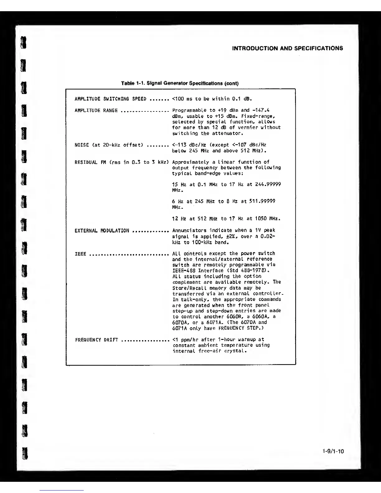
1-1.
Signal
Gonerator
Specifications (cent)
AMPLITUDE SWITCHING SPEED
<100
ms to be within 0.1 dB.
AMPLITUDE
RANGE
ProgrammabLe to +19 dBm and -U7.4
dBm, usable to
+15
dBm. Pixed-range,
selected by
special function, allows
for more than 12 dB of vernier
without
switching the attenuator.
NOISE Cat 20-kHz offset)
<-113
dBc/Hz (except
<-107 dBc/Hz
below
245 MHz and above 512 MHz).
RESIDUAL
FM Crms
in
0-3 to 3 kHz) Approximately a linear function of
output frequency between the
following
typical band-edge
values:
15 Hz at
0-1
MHz to 17 Hz at 244.99999
MHz.
6 Hz at 245 MHz to 8
Hi
at
511-99999
MHz.
12 Hz at 512
MHz
to
17
Hz at 1050
MHz.
EXTERNAL MODULATION
Annunciators indicate when a IV peak
signal
is applied, ±2%,
over a
0.02-
kHz to 100-kHz band.
IEEE All
controls
except the power switch
and
the
internal/external reference
switch
are remotely programmable
via
IEEE-488
Interface
(Std
488-1978).
ALL status including
the
option
complement are available
remotely.
The
Store/Recall
memory
data may be
transferred
via an external
controller-
In talk-only,
the appropriate
commands
are generated when
the front
panel
step-up and step-down
entries
are made
to control another
6060B,
a
6060A, a
6070A,
or a
6071 A. (The 6070A and
6071A only
have
FREQUENCY STEP.)
frequency
drift <1 ppm/hr
after
1-hour warmup at
constant
ambient
temperature using
internal
free-air
crystal.
1-9/MO