SCHEMATIC
DIAGRAMS
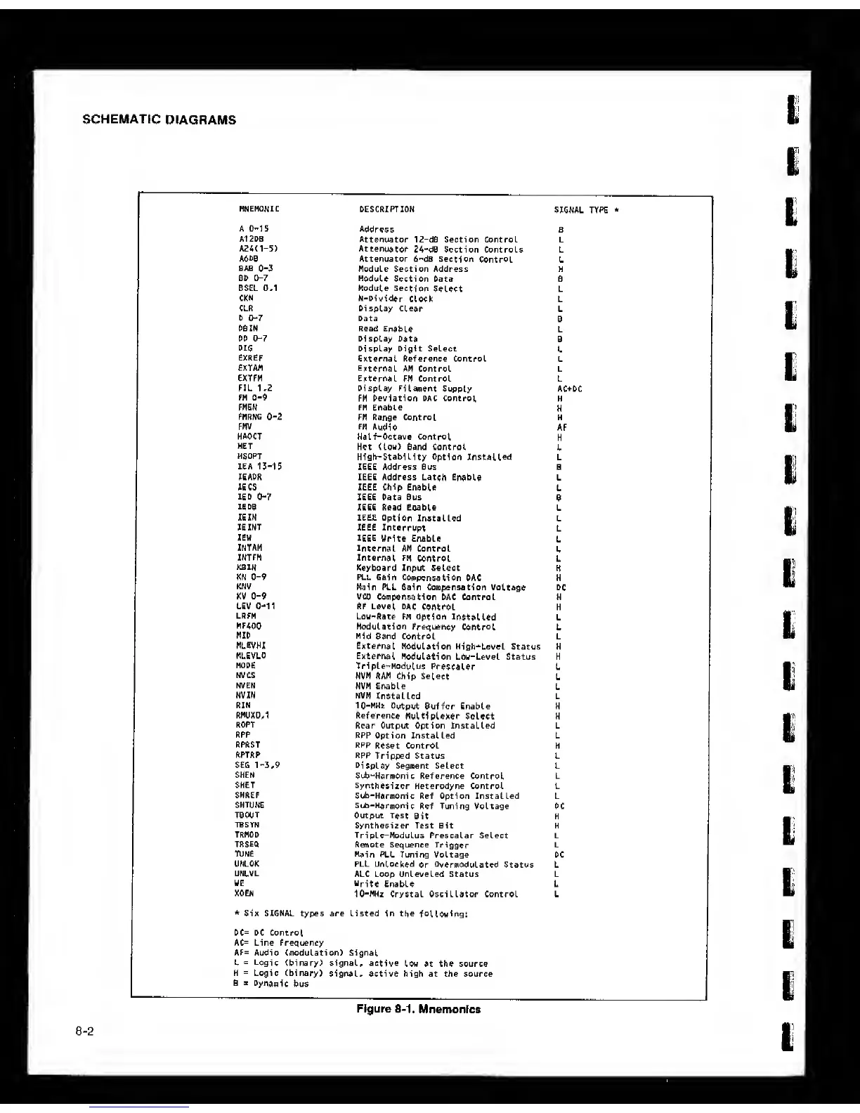
MNEMONIC
DESCRIPTION
SIGNAL TYPE
*
A
0-1
S
Address
B
A12DB
Attenuator 12-d6 Section Control L
A24(1-5)
Attenuator
24-dB Section Controls L
A6b0
Attenuator 6-dB Section
Control
L
BAB 0-3
Module Section Address H
0D
0-7
Module
Section Data S
BSEL 0,1 Module
Section
Select L
CKN N-Oivider
Clock L
CLR Display
Clear
L
0
0-7
Data
6
OBZN Read
Enable
L
00 t>-7 Display
Data
B
DIG
Display Digit Select
L
EXREF
External Reference Control L
exTAM
External
am Control L
EXTFM
External
fh Control L
FIL 1.2 Display
Filament
Supply AC+DC
FM
0-9
FM Deviation DAC Control
H
FMEN FM Enable
H
Fmrng
0-2
FM Range Control H
FMV
FH Audio
AF
HAOCT
Half-Octave
Control
H
HET
Hot
(Low) Band
Control
L
HSOPT
High-Stability
Option
Installed L
lEA
13-15
IEEE
Address Bus B
lEAOR IEEE Address Latch
Enable L
lECS IEEE Chip Enable
L
ISO 0-7
IEEE Data Bus
B
IE OB
IEEE Read Eoable
L
lEIN IEEE
Option
Installed L
JSINT IEEE
Interrupt
L
lEW
IEEE
Write Enable
L
INTAM
Internal
AM Control
L
xntfn Internal
FM
Control L
KBIN
Keyboard Input Select
H
KN
0-9
PLL Gain
Compensation
OAC H
KNV
Main PLL Gain Compensation
Voltage DC
KV
0-9
vco
Compensation OAC Control H
UEV
0-11
RF Level
DAC
Control H
LRFM
Low-Rate FM Option
installed
L
MF400
Modulation Frequency
Control
L
HID
Mid
Band Control L
MLEVHI External
Modulation High-Level Status H
MLEVLO
External
Modulation Low-Level Status H
MODE
Triple-Modulus
Prescaler L
NVCS
NVM RAM Chip
Select
L
NVEN
NVM Enable
L
NVIN NVM
Installed L
RIN 10-MHt
Output Buffer Enable H
RMUXD,1 Reference
Multiplexer Select H
ROPT
Rear Output Option Installed L
ftPP
RPP Option Installed L
RPRST RPP
Reset Control H
RPTftP
RPP
Tripped Status L
SEfi
1-3,9
Display
Segment Select L
SHEN
Sub-Harmonic Reference Control L
SHET
Synthesizer
Heterodyne Control L
SHREF
Sub-HarmOnic
Ref Option Installed L
SHTUNE
Sub-Harmonic
Ref Tuning Voltage DC
TBOOT Output
Test
Bit K
TBSYN
Synthesizer Test Bit H
TRMOO
Triple-Modulus Prescalar Select L
TRSEQ
Remote Sequence Trigger L
TUNE
Main
PLL Tuning Voltage DC
UNLOK PLL Unlocked
or
OvermOdulated
Status L
UNI.VL
ALC Loop Unleveled Status L
WE
Write
Enable L
XOEN
10-MHz Crystal Oscillator Control L
*
S-ix SIGNAL types are listed
in
the
following:
0C= DC Control,
AC= Line Frequency
AF= Audio (modulation) Signal
L
=
Logi
c (binary) signal,
active
low at the source
H
=
Logic (binary)
signal, active high at the source
0
B
Dynamic
bus
Figure 8-1.
Mnemonics
8-2