INSTALLATION AND OPERATION
Table
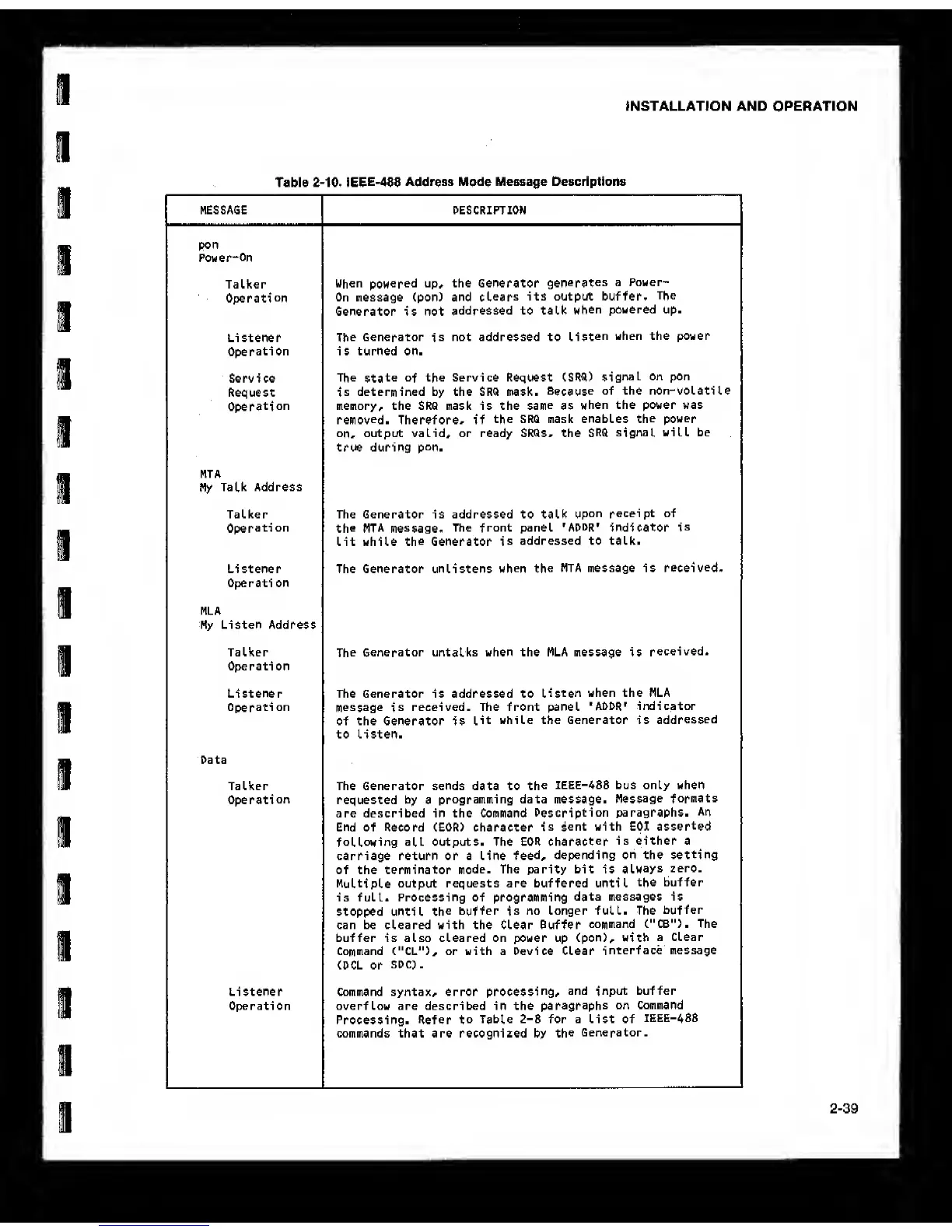
2-10. IEEE-488
Address
Mode
Message Descriptions
MESSAGE DESCRIPTION
pon
Power“0n
TaLker
Operation
When
powered
up, the Generator
generates
a Power-
On message (pon) and
clears
its output buffer.
The
Generator is not
addressed to talk
when
powered up.
Listener
Operation
The
Generator
is
not addressed to
Listen
when the power
is turned on.
Service
Request
Operation
The
state of
the Service Request (SRQ)
signal on pon
is
determined by the SRQ mask.
Because
of the non-volatile
memory, the SRQ mask is the
same
as
when the power was
removed.
Therefore, if
the SRQ mask enables
the power
on,
output valid, or ready SRQs, the
SRQ
signal will be
true during
pon.
MTA
My
Talk Address
TaLker
Operation
The Generator is addressed to talk
upon receipt of
the MTA message.
The front panel
'ADDR'
indicator
is
Lit while
the
Generator
is
addressed to talk.
Listener
Operation
The Generator unlistens
when the
MTA message is
received.
MLA
My Listen Address
TaLker
Operation
The
Generator untalks when the MLA message is
received.
Listener
Operati on
The Generator is addressed to
listen
when the MLA
message
is
received. The front panel
'ADDR'
indicator
of the Generator is
lit while the Generator is
addressed
to listen.
Data
TaLker
Operation
The Generator sends data to
the
IEEE-488 bus only when
requested by a
programming data message.
Message
formats
are described in the Command
Description
paragraphs.
An
End of Record (EOR) character
is
sent with EOI
asserted
following
all outputs. The EOR
character
is either a
carriage return or a Line
feed,
depending on the setting
of the terminator
mode.
The parity bit is
always
zero.
Multiple output
requests are buffered until
the buffer
is full. Processing of programming
data messages is
stopped until
the
buffer
is
no longer full. The
buffer
can be cleared with the Clear Buffer
command C"CB"). The
buffer is also cleared on power up (pon), with
a Clear
Command ("CL"), or with a Device Clear
interface message
(DCL or
SDC).
Listener
Operation
Command syntax, error
processing,
and input buffer
overflow are described in the
paragraphs
on Command
Processing, Refer
to
Table
2-8
for a List of
IEEE-4S8
commands that are recognized by
the
Generator.
2-39