INSTALLATION AND OPERATION
Table
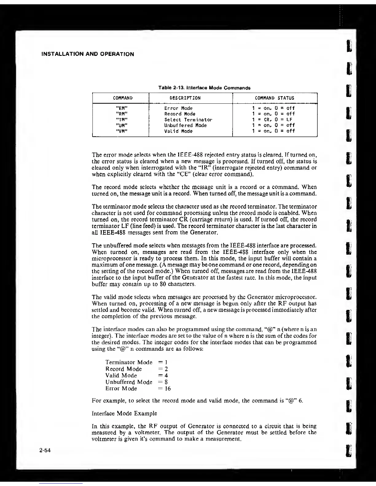
2-13.
Interfade
Mode
Commands
1
COMMAND DESCRIPTION
COMMAND STATUS
"EM" Error Mode 1
-
on,. 0
s
off
"RM" Record
Mode
1
=
on, 0
=
off
"TM" Select Terminator 1
=
CR, 0
=
LF
"UM"
Unbuffered Mode 1
=
on, 0
=
off
"VM" Valid Mode 1
=
on, 0
~
off
The
error
mode selects when the IEEE-488 rejected entry
status
is cleared.
If
turned on,
the error status is cleared
when
a
new
message is processed. If turned off, the status
is
cleared only when interrogated
with
the “IR” (interrogate rejected entry) command
or
when explicitly cleared with the “CE” (clear error command).
The record mode selects whether the message unit is a record or a command. When
turned
on,
the message unit is a record. When turned off, the
message
unit
is
a command.
The terminator mode selects
the character used
as the
record terminator.
The
terminator
character is not used for command processing unless the record mode is enabled.
When
turned on, the record terminator CR (carriage return) is used. If turned off, the record
terminator LF (line feed) is used. The record terminator character is the last character in
all IEEE-488 messages
sent from the Generator.
The unbuffered mode selects when messages from the IEEE-488 interface are processed.
When
turned on,
messages are read from the IEEE-488 interface only when the
microprocessor
is ready to process them. In this mode, the input buffer will contain a
maximum of one message. (A message may be one command or one record, depending on
the
setting of the record mode,) When turned off, messages are read from the IEEE-488
interface to
the
input buffer of the Generator at the
fastest rate.
In
this
mode,
the input
buffer may contain up to 80
characters.
The valid mode selects when messages are processed by the Generator microprocessor.
When turned on, processing of a new message is begun only after the RF output has
settled and become valid. When turned off, a new message is processed immediately after
the completion of the previous message.
The
interface modes can also be programmed using the command, n (where n
is
an
integer). The
interface modes
are
set
to
the value
of n where n is the sum of the codes for
the desired modes. The integer codes for the interface modes that can be programmed
using
the n commands are as follows:
Terminator Mode
-
1
Record
Mode
=
2
Valid Mode
-
4
Unbuffered
Mode
=
8
Error
Mode
=
16
For example, to select the record mode and valid mode, the command is 6.
Interface Mode Example
In this example, the RF output
of
Generator is connected to a circuit that
is being
measured by a
voltmeter. The output of the
Generator
must
be
settled
before
the
voltmeter is
given
it’s command to make a measurement.
2-54