Maintenance
PERFORMANCE
TEST
5.
Set the Current Source for zero
mA
and disconnect it
from the 8840A.
6-8.
AC Current Test (Option
-09
Only)
The following procedure may
be
used to test the mA AC
function:
Ensure the
8840A is on and warmed up for at least
1
hour.
Select the mA AC function.
Connect the AC Current Source to provide a current
input
to
the 2A and
LO
INPUT terminals.
If
an ac
current source is not available, the functionality of the
8840A
can
be
checked at 10
rnA
by using
a
Fluke
5200A
set
at lOOV and
COMX~~
to the 884OA 2A
terminal through a 10
kS2,
2W,
1% resistor.
For each step in Table
6-7,
set the AC Current Source
for the indicated input and verify that the displayed
reading is within the limits shown for each reading
rate.
Set the AC Current Source to Standby and disconnect
it from the
8840A.
CAUTION
To avoid uncalibrating the
8840A,
never
cycle power on
or
off while the
CAL
ENABLE
switch
is
on.
NOTE
If
U220
is
replace4 perform the Erase Cali-
bration Memory procedure (located later in
this section) before attempting calibration.
Failure
to
do
so
may
result in an ERROR
29
on the 8840A front panel display.
The 8840A features closed-case calibration using known
reference sources. The 8840A automatically prompts you
for the required reference sources, measures them, calcu-
lates correction factors, and stores the correction factors in
the nonvolatile calibration memory.
Closed-case calibration has many advantages. There are no
parts to disassemble, no mechanical adjustments to make,
and if the IEEE-488 Interface is installed, the
8840A can
be
calibrated by an automated instrumentation system.
The 8840A should normally
be
calibrated on a regular
cycle, typically every 90 days or
1
year. The frequency of
the calibration cycle depends on the accuracy specification
you wish to maintain. The
8840A should also be calibrated
if it fails the performance test or has undergone repair.
To
meet the specifications in Section
1,
the 8840A should be
calibrated with equipment meeting the minimum
specifications given in Table
6-1.
The following paragraphs first present a basic calibration
procedure. This is followed by
a
description of advanced
features and special considerations, and by a description of
remote calibration using the
IEEE-488
Interface.
6-10.
Basic Calibration Procedure
The lbasic calibration procedure consists of the following
four parts. These parts must
be
performed in the order
shown.
1.
Initial Procedure.
2.
AID
Calibration.
3.
Offset and
Gain
Calibration for each function and
range.
4. High-Frequency AC Calibration (True RMS AC
option only).
Normally, it is recommended that the entire calibration
procedure
be
performed. However, under some circum-
stances the earlier parts may
be
omitted. For example,
if
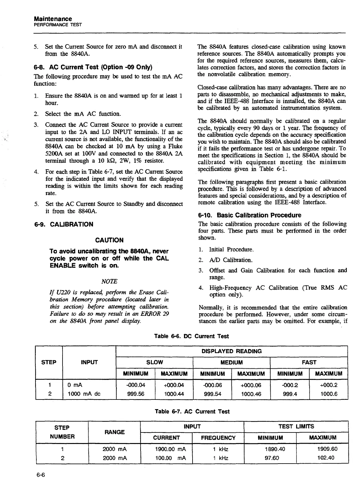
Table
6-6.
DC
Current Test
Tabie
6-7.
AC Current Test
STEP
1
2
INPUT
0 mA
1000 mA
dc
STEP
NUMBER
1
2
DISPLAYED READING
RANGE
2000 mA
2000 mA
SLOW
MINIMUM
-000.04
999.56
INPUT
MAXIMUM
+000.04
1000.44
MEDIUM
TEST
LIMITS
CURRENT
1900.00 mA
100.00 mA
FAST
MINIMUM
-000.06
999.54
MINIMUM
1
890.40
97.60
FREQUENCY
1
kHz
1
kHz
MINIMUM
-000 2
999.4
MAXIMUM
+000.06
1000.46
MAXIMUM
1 909.60
102.40
MAXIMUM
+000.2
1000.6
Artisan Technology Group - Quality Instrumentation ... Guaranteed | (888) 88-SOURCE | www.artisantg.com