Remote
Programming
DEVICE-DEPENDENT
COMMAND
SET
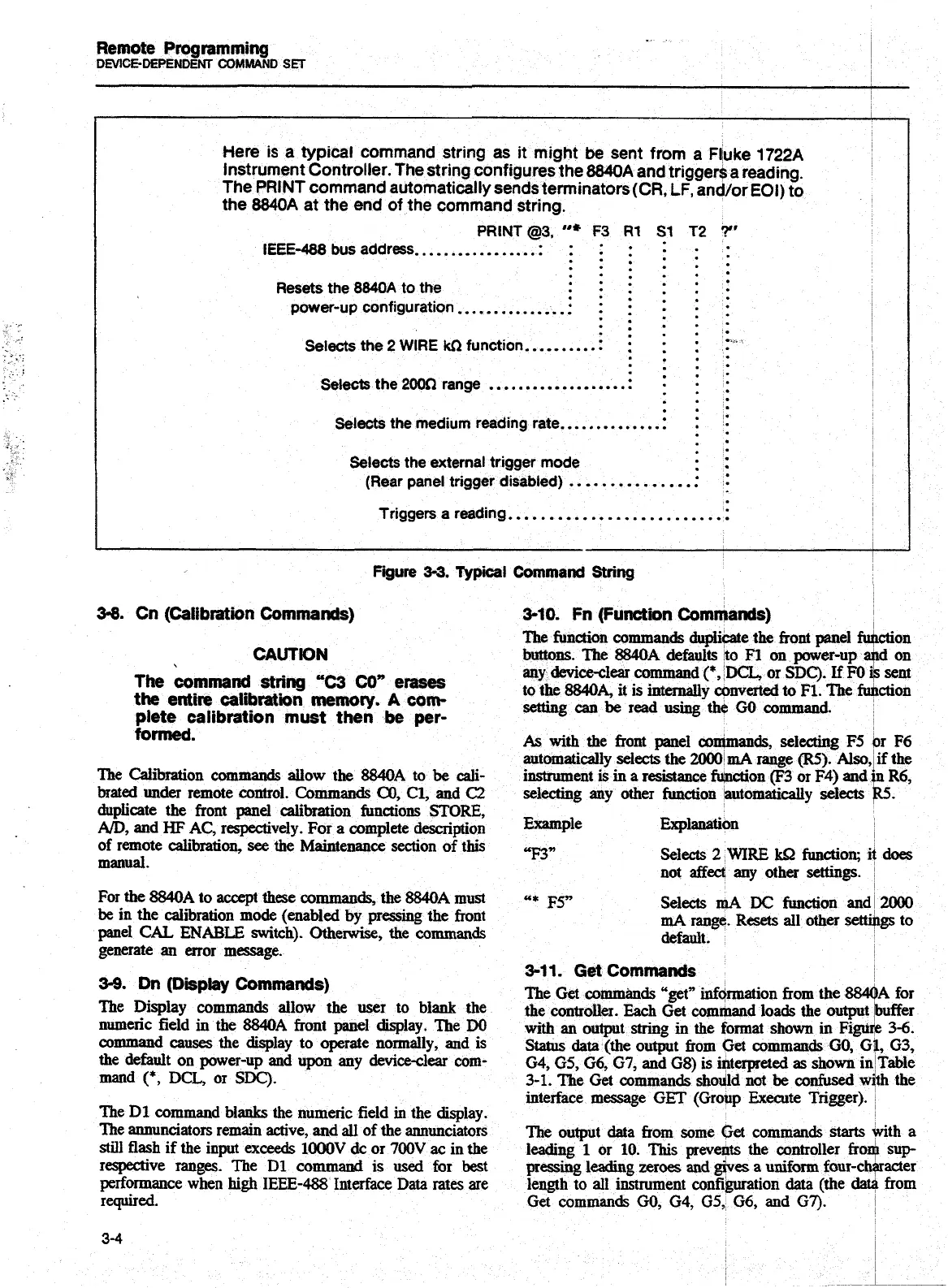
Here is
a
typical command string
as
it might be sent from
a
Fl;uke
1722A
Instrument Controller. The string configures the
8840A
and trigger$
a
reading.
The
PRINT
command automatically sends terminators
(CR,
LF,
and/or EOl) to
the
8840A
at the end of the command string.
PRINT
@3,
"*
F3
R1
S1
T2
?"
....
IEEE-488 bus address..
...................
..-
......
......
......
......
Resets the
8840A
to the
.-.
...
... ...
...
...
power-up configuration
..................
.....
.....
.....
.......
..............
Selects the
2
WIRE
kn
function.
....
....
...
Selects the
2002)
range
..................
.:
...
...
-..
...
...
.................
Selects the medium reading rate
.-
.
.
.
Selects the external
trigger
mode
. .
.-
(Rear panel trigger disabled)
.................
........................
Triggers a reading..
:
I
figure
3-3.
Typical
Command
String
3-8.
Cn (Calibration Commands)
3-10.
Fn (Function Commands)
The function commands duplicate the
front
panel
ft
CAUTION
buttons.
The
8840A
defaults
to
M
on power-up
r
The
command
string
"C3 CO"
erases
any deviceclear command
(*,
'DCL,
or
SDC).
If
FO
the
entire calibratiin
memory.
A
com-
to the
884014,
it is internally
converted
to
F1. The
fi
plete calibration must then
be
per-
setting
can
be
read
using
the
GO
command.
formed.
As
with
the front panel wntmands, seleaing
F5
automatically
selects
the
UWX)lmA
range
(R5).
Also
The Cai~Won commands allow the
8840A
to
be
cali-
instrument
is
in
a
resistance Won (F3 or
F4)
and
brated
under
remote control. Commands
CO,
C1,
and
C2
selecting any other function kutomatically selects
duplicate the front
panel
calibration functions
STORE,
AD,
and
HF
AC,
respectively. For a complete description
Jihplanation
of remote calibration,
see
the
Maintenance section of this
manual.
Selects
2
WIRE
U2
function;
not
affect
any
other
settings.
For
the
8840A
to
accept
these
commds,
the
8840A
must
-*
F5"
Selects
mA
DC
function
anc:
be
in the calibration mode (enabled by pressing the front
mA
range. Resets all other
sett
panel
CAL
ENABLE
switch).
Otherwise,
the commands
default.
generate
an
error message.
3-1
1.
Get
Commands
3-9.
Dn
(Dipby Commands)
The Get commimds
"get"
infqrmation from the
8&
The Dis@~ com~nds allow the
to blank the
the contrcdler.
Each
Get command loads the outpu
nUnIeric field
in
the
MA
front panel display. The
W
dth
an
output string
in
the format shown in Fig
mmmand
causes
the -lay to operate nomdly,
and
is
Status
data
(the output from Get commands
GO,
(
the default on power-up and upon any
device-clear
corn-
G4,
GS,
G6,
G7,
and G8) is interpreted as shown i
mand
(*,
DCL,
or
SDC).
3-1. The
Get
commands shodld not
be
confused
s
interface message
GET
(Group Execute Trigger)
The
Dl
command blanks the numeric field
in
the display.
The annunciators remain active, and
all
of the annunciators
The output data from some
Get
commands
starts
still flash if the input
exceeds
lOOOV
dc
or
700V
ac
in
the
leading
1
or
10.
This prevents the controller frc
respective
ranges.
The Dl command
is
used
for
best
pressing
leading zeroes
and
gives
a
uniform four-c
performance when
high
IEEE-488
Interface Data rates
are
length to all instrument configuration data (the
&
required.
Get commands
GO,
G4,
G5,
G6, and
G7).
3-4
ction
d
on
sent
ction
r
F6
f
the
1
R6,
5.
does
1A
for
buffer
3-6.
1,
(33,
Table
th
the
vith a
l
sup
uacter
from
Artisan Technology Group - Quality Instrumentation ... Guaranteed | (888) 88-SOURCE | www.artisantg.com