Operating instruc8ions
OPERATING
FWTURES
OVER
1
I
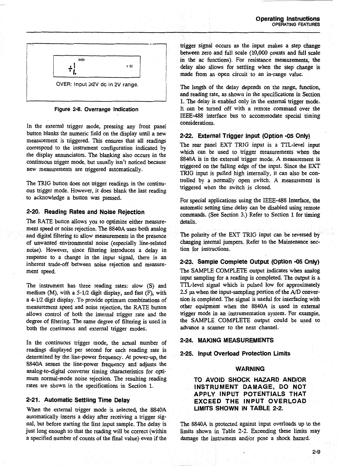
OVER:
input
22V
dc
in
2V
range.
I
Figure
2-8.
Overrange Indication
In the external trigger mode, pressing any front panel
button blanks the numeric field on the display until a new
measurement is triggered. This ensures that all readings
correspond to the instrument configuration indicated by
the display annunciators. The blanking also occurs in the
continuous trigger mode, but usually isn't noticed because
new measurements are triggered automatically.
The TRIG button does not trigger readings in the continu-
ous trigger mode. However, it does blank the last reading
to acknowledge a button was pressed.
2-20. Reading Rates and Noise Rejection
The RATE button allows you to optimize either measure-
ment speed or noise rejection. The 8840A uses both analog
and digital filtering to allow measurements in the presence
of unwanted environmental noise (especially line-related
noise). However, since filtering introduces a delay in
response to a change in the input signal, there is an
inherent trade-off between noise rejection and measure-
ment speed.
The instrument has three reading rates: slow
(S)
and
medium
(M),
with a
5-112
digit display, and fast
(F),
with
a 4-112 digit display. To provide optimum combinations of
measurement speed and noise rejection, the
RATE
button
allows control of both the internal trigger rate and the
degree of filtering. The same degree of filtering is used in
both the continuous and external trigger modes.
In
the continuous trigger mode, the actual number of
readings displayed per second for each reading rate is
determined by the line-power frequency. At power-up, the
8840A senses the line-power frequency and adjusts the
analog-to-digital converter timing characteristics for opti-
mum normal-mode noise rejection. The resulting reading
rates are shown in the specifications in
Section
1.
2-21. Automatic Settling Time Delay
When the external trigger mode is selected, the
8840A
automatically inserts
a
delay after receiving
a
trigger sig-
nal, but before starting the first input sample. The delay is
just long enough so that the reading will be correct (within
a specified number of counts of the final value) even if the
trigger signal occurs
as
the input makes a step change
between zero and full scale
(10,000
counts and full scale
in the ac functions). For resistance measurements,
the
delay also allows for settling when the step change is
made from
an
open circuit to an in-range value.
The length of the delay depends on the range, function,
and
reading rate, as shown in the specifications in Section
1.
The delay is enabled only in the external trigger mode.
It
can
be turned off with a remote command over
the
IEEE-488 interface bus to accommodate special timing
considerations.
2-22. External Trigger lnput (Option -05 Only)
The rear panel EXT TRIG input is a ?TL-level input
which
can
be
used to trigger measurements when the
8840A is in the external trigger mode. A measurement
is
triggered on the falling edge of the input. Since the
EXT
TRIG
input is pulled high internally, it can also be con-
trolled by a normally open switch.
A
measurement is
triggered when the switch is closed.
For special applications using the IEEE-488 Interface, the
automatic setting time delay
can
be disabled using remote
commands. (See Section
3.)
Refer to Section
1
for timing
details.
The polarity
of
the EXT TRIG input
can
be reversed
by
changing internal jumpers. Refer to the Maintenance
sec-
tion for instructions.
2-23. Sample Complete Output (Option
-05
Only)
The SAMPLE COMPLETE output indicates when analog
input sampling for a reading is completed. The output is a
TTL-level signal which is pulsed low for approximately
2.5
p
when the input-sampling portion of the
AD
conver-
sion is completed. The signal is useful for interfacing with
other equipment when the 8840A is used in external
trigger mode in an instrumentation system. For example,
the SAMPLE COMPLETE output could be used to
advance a scanner to the next channel.
2-24. MAKING MEASUREMENTS
2-25. lnput Overload Protection Limits
WARNING
TO AVOID SHOCK HAZARD
AND/OR
INSTRUMENT DAMAGE, DO NOT
APPLY INPUT POTENTIALS THAT
EXCEED THE INPUT OVERLOAD
LIMITS SHOWN IN TABLE 2-2.
The 8840A
is
protected against input overloads up to the
limits shown in Table
2-2.
Exceeding these limits may
damage the instrument andlor pose a shock hazard.
Artisan Technology Group - Quality Instrumentation ... Guaranteed | (888) 88-SOURCE | www.artisantg.com