Maintenance
CAUBRATION
a.
STORE
--
Erases the entire memory.
b.
AD
--
Erases the
A/D
Calibration constants
c. Any function button
--
Erases the Offset and Gain
Calibration constants for all ranges of that func-
tion.
d.
HF
AC
--
Erases the High-Frequency
AC
Calibra-
tion constants.
3.
After
an
erasure is finished
(a
complete erasure
takes
about
3
seconds), the 8840A returns to one of the
following states:
a.
After complete erasure: Begins
AID
Calibration.
b. After
AD
erasure: Begins
A/D
Calibration.
c. After Offset and Gain erasure: Begins Offset and
Gain Calibration for erased function.
d.
After High-Frequency AC erasure: Begins
High-
Frequency AC Calibration.
6-20.
TOLERANCE CHECK
The 8M0A automatically checks that the reference input is
near the value prompted. This minimizes common errors
such
as
applying
a
reference source with the wrong sign. If
the reference input exceeds the tolerances shown in Table
6-13, the
8840A displays ERROR 41.
If ERROR 41 occurs, the most likely cause is that the
reference input is incorrect (e-g., has the wrong polarity).
If the input is in fact correct, refer to the Troubleshooting
heading in this section.
6-21.
AC
CALIBRATION AT OTHER
FREQUENCIES
For special applications where the 8840A is to
be
used to
measure ac voltages or currents exclusively at a single
frequency or narrow range of frequencies,
accuracy may
be
enhanced at that frequency (or range of frequencies) by
performing calibration according to the following proce-
dure. Note that this may degrade the accuracy at frequen-
cies significantly removed from the frequency of
optimization.
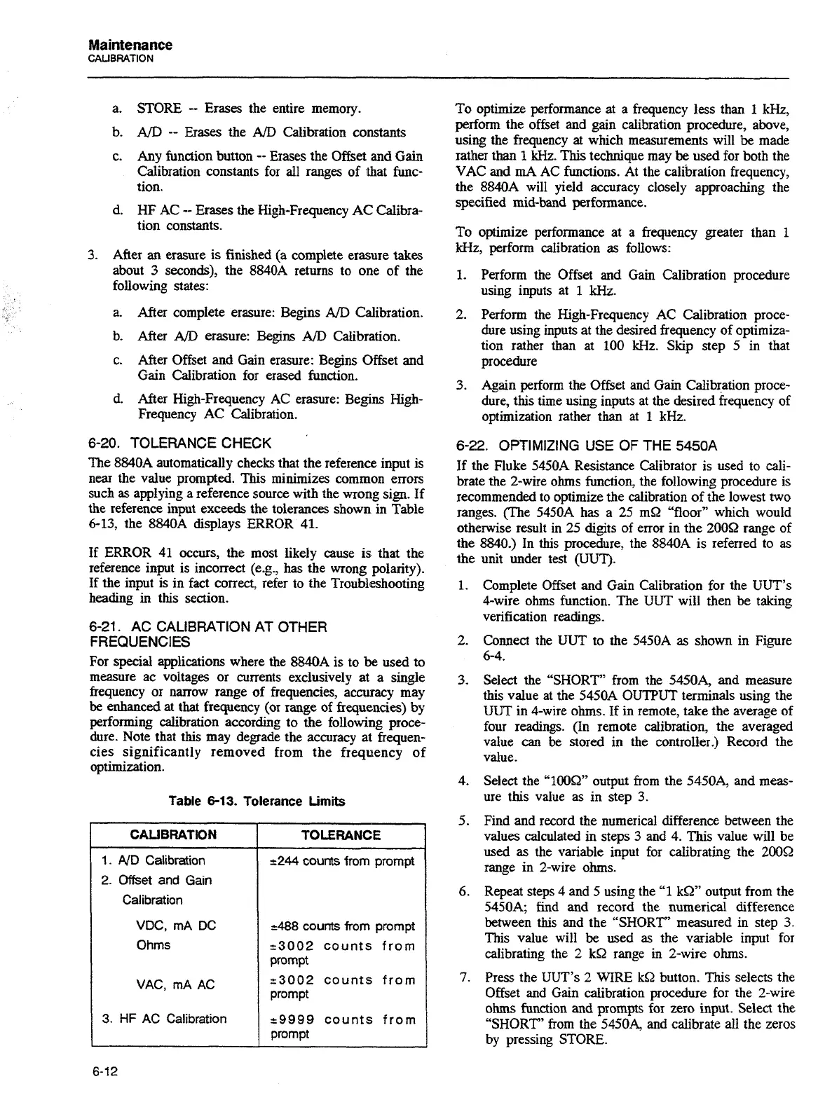
Table
6-13.
Tolerance
Limits
CALIBRATION
1.
ND Calibration
2.
Offset
and Gain
Calibration
VDC, mA DC
Ohms
VAC, mA AC
3.
HF
AC Calibration
488
counts from prompt
-3002
counts from
prompt
-3002
counts from
prompt
-9999
counts from
prompt
To optimize performance at a frequency less than
1
kHz,
perform the offset and gain calibration procedure, above,
using the frequency at which measurements will
be
made
rather than
1
kHz.
This
technique may
be
used for both the
VAC
and
mA
AC functions. At the calibration frequency,
the 8840A will yield accuracy closely approaching the
specified mid-band performance.
To optimize
performance at a frequency greater than
1
kHz, perform calibration
as
follows:
1.
Perform the Offset and Gain Calibration procedure
using inputs at
1
kHz.
2. Perform the High-Frequency AC Calibration proce-
dure using inputs at the desired frequency of optimiza-
tion rather than at 100 kHz. Skip step
5
in that
procedure
3.
Again perform the Offset and Gain Calibration proce-
dure, this time using inputs at the desired frequency of
optimization rather than at
1
kHz.
6-22.
OPTIMIZING USE OF THE 5450A
If t,he Fluke 5450A Resistance Calibrator is used to cali-
brate the 2-wire ohms function, the following procedure is
recommended to optimize the calibration of the lowest two
ranges. (The
5450A
has
a 25 m9 "floor7' which would
otherwise result in 25 digits of error in the 2009 range of
the
8840.) In this procedure, the 8840A is referred to
as
unit under test
@JUT).
the
1.
2.
3.
4.
5.
6.
7.
Complete Offset and Gain Calibration for the UUT's
4-wire ohms function. The UUT will then be taking
verification readings.
Connect the
UUT
to the 5450A
as
shown in Figure
64.
Select the "SHORT" from the
5450A, and measure
this value at the 5450A OUTPUT terminals using the
UUT
in 4-wire ohms. If in remote, take the average of
four readings. (In remote calibration, the averaged
value
can
be stored in the controller.) Record the
value.
Select the "100S2" output from the 5450A, and meas-
ure this value as in step
3.
Find and record the numerical difference between the
values calculated in steps
3
and 4. This value will be
used
as
the variable input for calibrating the 2009
range in 2-wire ohms.
Repeat steps 4 and 5 using the
"1
kW
output from the
5450A; find and record the numerical difference
between this and the "SHORT' measured in step
3.
This value will
be
used as the variable input for
calibrating the
2
kQ range in 2-wire ohms.
Press the UUT's
2
WIRE
kS2
button. This selects the
Offset and Gain calibration procedure for the 2-wire
ohms function and prompts
for zero input. Select the
'SHORT"
from the 54504 and calibrate all the zeros
by pressing STORE.
Artisan Technology Group - Quality Instrumentation ... Guaranteed | (888) 88-SOURCE | www.artisantg.com