I
ERROR
1
I
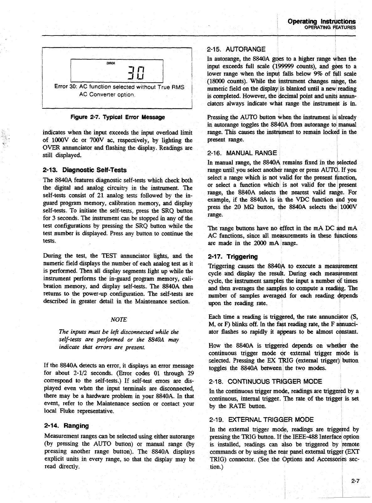
Error
;o:
AC
funct~ov selected wlthout The
RMS
I
I
AC
Converter option
!
Figure
2-7.
Typical Error
Message
indicates when the input exceeds the input overload limit
of lOOOV dc or
700V
ac, respectively, by lighting the
OVER
annunciator and flashing the display. Readings are
still displayed.
2-1
3.
Diagnostic
Self-Tests
The 8840A features diagnostic self-tests which check both
the digital and analog circuitry in the instrument. The
self-tests consist of
21
analog tests followed by the in-
guard program memory, calibration memory, and display
self-tests. To initiate the self-tests, press the
SRQ
button
for
3
seconds. The instrument
can
be
stopped in any of the
test configurations by pressing the
SRQ
button while the
test number is displayed. Press any button to continue the
tests.
During the test, the
TEST
annunciator lights, and the
numeric field displays the number of each analog test
as
it
is performed. Then all display segments light up while the
instmment performs the in-guard program memory, cali-
bration memory, and display self-tests. The
8840A then
returns
to
the power-up configuration. The self-tests are
described in greater detail in the Maintenance section.
NOTE
The
inputs must be
lefi
disconnected while
the
self-tests are performed
or
the
8840A
nqv
indicate that errors
are
present.
If the 8840A detects
an
error, it displays an error message
for about 2-112 seconds. (&or codes
01
through
29
correspond to the self-tests.) If self-test errors are
dis-
played even when the input terminals are disconnected,
there may
be
a hardware problem in your 8840A. In that
event, refer to the Maintenance section or contact your
local Fluke representative.
2-14.
Ranging
Measurement ranges can
be
selected using either autorange
(by pressing the AUTO button) or manual range (by
pressing another range button). The 8840A displays
explicit units in every range, so that the display may be
read directly.
2-1
5.
AUTORANGE
In autorange, the 8840A
gqes
to a higher range when the
input exceeds full scale
(1b9999
counts), and
gbes
to a
lower range when the input falls below
9%
of
fGIl
scale
(18000 counts). While the instmment changes rallge, the
numeric field on the display, is blanked until a new reading
is completed. However, the decimal point and unit$ annun-
ciators always indicate what range the instrumen/lt
is
in.
Pressing the AUTO button when the instrument is1 already
in autorange toggles the 884OA from autorange to
manual
range.
This
causes the instwent to remain lock& in the
present range.
2-16.
MANUAL RANGE
In manual range, the 8840A remains fixed in the Selected
range until you select another range or press
AUTC/.
If you
select a range which
is
not valid for the present Gction,
or select a function which is not valid for the present
range, the
8840A selects the nearest valid ranbe. For
example, if the 8840A is in the
VDC
function
and
you
press the 20
MQ
button, the 8840A selects the lOOOV
range.
The range buttons have no effect in the
mA
DC
and mA
AC functions, since all measurements in these fdnctions
are made in the
2000
mA range.
2-17.
Triggering
Triggering causes the 88406 to execute a mearement
cycle
and
display the result. During
each
m
cycle, the instrument samples the input a
and
then averages the sampi'ps
upon the reading rate.
number of samples averagetd
Each time a reading is triggered, the rate annunciator
(S,
M,
or
F)
blinks off. In the fast reading rate, the
F
ahnunci-
ator flashes
so
rapidly it appears to
be
almost Tnstant.
How the 8840A
is
triggered depends on
whetker
the
continuous trigger mode dr external trigger dode is
selected. Pressing the
EX
TRIG
(external trigger) button
toggles the 8840A between the two
modes.
2-1
8. CONTINUOUS
TRIGGER
MODE
In the continuous trigger mode, readings are triggered by a
continuous, internal trigger. The rate of the trigget is set
by the
RATE
button.
2-1
9.
EXTERNAL
TRIGGER
MODE
In the external trigger mode, readings are triggeled by
pressing the
TRIG
button. If the IEEE-488 Interface option
is installed, readings can aiso be triggered by Jremote
commands or
by
using the
rear
panel external trigge);
(EXT
TRIG)
connector. (See the Options and Accessories sec-
tion.)
I
2-7
I
Artisan Technology Group - Quality Instrumentation ... Guaranteed | (888) 88-SOURCE | www.artisantg.com