Maintenance
CAUBRATiON
NOTE
6-27.
DISASSEMBLY PROCEDURE
When erasing calibration memory, it is good
practice to send the communds
C3
and
CO
in
WARNING
the same command string. Sending
C3
by itself
TD
AVOID ELECTRIC SHOCK, REMOVE
could lead to accidentally erasing calibration
VE POWER CORD AND TEST LEADS
memory, since the
C3
command does not time
&FORE DISASSEMBLING THE IN$TRU-
out
as does the
ERASE
button.
MEW.
OPENING COVERS
MAY
EXPOSE
LIVE PARTS.
CAUTION
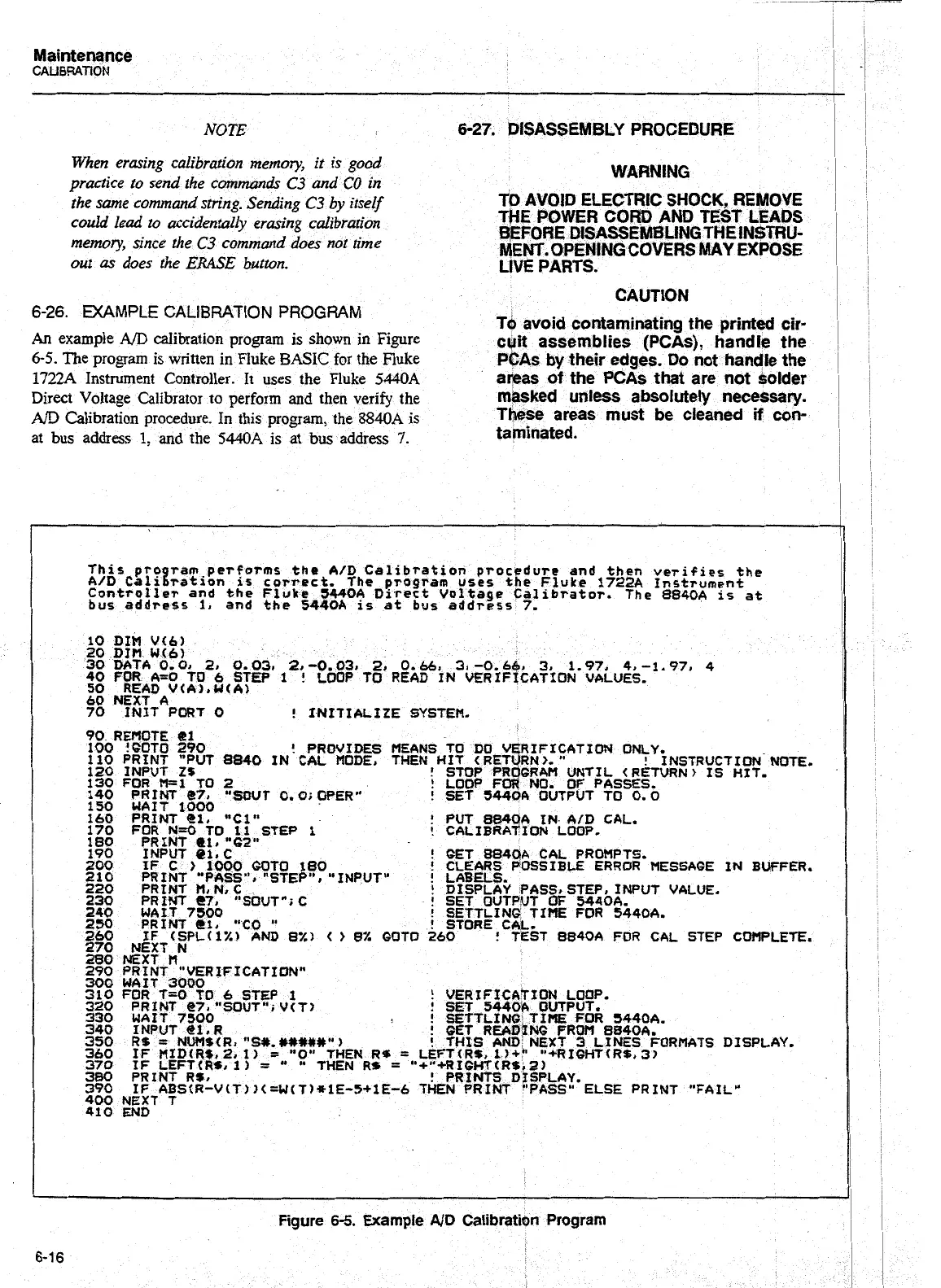
6-26.
EXAMPLE CALIBRATION PROGRAM
Tcb avoid contaminating the printed cir-
An
example
A/D
calibration program is shown in Figure
cyit assemblies (PCAs), handle the
6-5.
The program is written in Fluke
BASIC
for the Fluke
PCAs by their edges. Do not handle the
1722A
Instrument Controller.
It
uses the Fluke
5440A
areas
of
the PCAs that are not solder
Direct Voltage Calibrator to perform and then verify the
m&ked unless absoIutely necessary.
A/D
Calibration procedure. In this program, the
8840A
is
These areas must be cleaned
if
con-
at bus address
1,
and
the
544.014
is
at
bus
address
7.
taminated.
This
pro
ram performs the
A/D
Calibration procedure and then verifies
the
AD
~liraton
1s
correct.
The
program
uses
the Fluke
172
Instrument
Controller and the Fluke
5440A
Direct Voltage Calibrator. The 8840A
is
at
bus address
1,
and the
5440A
is at bus address
7.
10
DIM
V(6)
20
DJH
Wt6)
30
DATA
0-
01
21
0.031
2r
-0.03,
2,
0.661
3.
-0.6
3,
1-97,
4,
-1.97,
4
40
FOR As0
TO
6
STEP
1
!
LOOP
TO
READ
IN VERIF~~ATION VALUES.
50
READ V(A).U(A)
60
NEXT
A
70
INIT
PORT
0
!
INITIALIZE
SYSTEM.
Artisan Technology Group - Quality Instrumentation ... Guaranteed | (888) 88-SOURCE | www.artisantg.com