Maintenance
TROUBLESHOOTlNG
generate problems that may
be
difficult to locate and
repair. However, such failures will in turn cause failures in
some analog and or digital section. Thus, indirectly,
troubleshooting the affected section will lead to
correction
of problems in the internal bus or guard-crossing circuit.
6-38.
Diagnostic Self-Tests
To run the diagnostic self-tests,
~~SCOM~C~
the test leads
and press the SRQ button for
3
seconds. If the test leads
are left attached to the input terminals the 8840A may
indicate errors are present (most likely, errors
5,
7,
8,
9,
and 10). Also, if the FRONTREAR switch is in the
REAR position, the 8840A skips tests
3
and
4,
and if
Option
-09
is not installed, the 8840A skips tests 1,
2,
and
3.
For
all
tests, there is a 0.5 second delay period before
any readings are taken. The tests are all contingent on the
A/D Converter being properly calibrated, but do not
depend on the
Offset
and
Gain
Calibration constants.
Failing the tests indicates that key portions of the 8840A
are not performing properly. Passing the tests gives
approximately a
90%
probability that all
VDC
]ranges and
range r6 of Zwire ohms can
be
calibrated.
Passing
the
tests also
gives
a
reasonable probability that
it
will give
accurate measurements in VDC and range r6 of 2-wire
ohms. However, passing the tests does not guarantee that
TEST
NUMBER
TEST
POINT
the instrument can
be
calibrated in VAC,
mA
DC, mA
AC, 4-wire ohms, or ranges rl to r5 of 2-wire ohms.
NOTE
If
the AID Converter or Precision Voltage
Reference
is
not working, all analog tests
would show an error.
If
the AID Converter is
not calibrated tests
7,
15,
19
could show
an
error.
If the analog self-tests indicate an error, it may be possible
to isolate the problem
as
follows:
1.
While the error code is being displayed, press the
SRQ button. This latches the 8840A into the particular
test configuration.
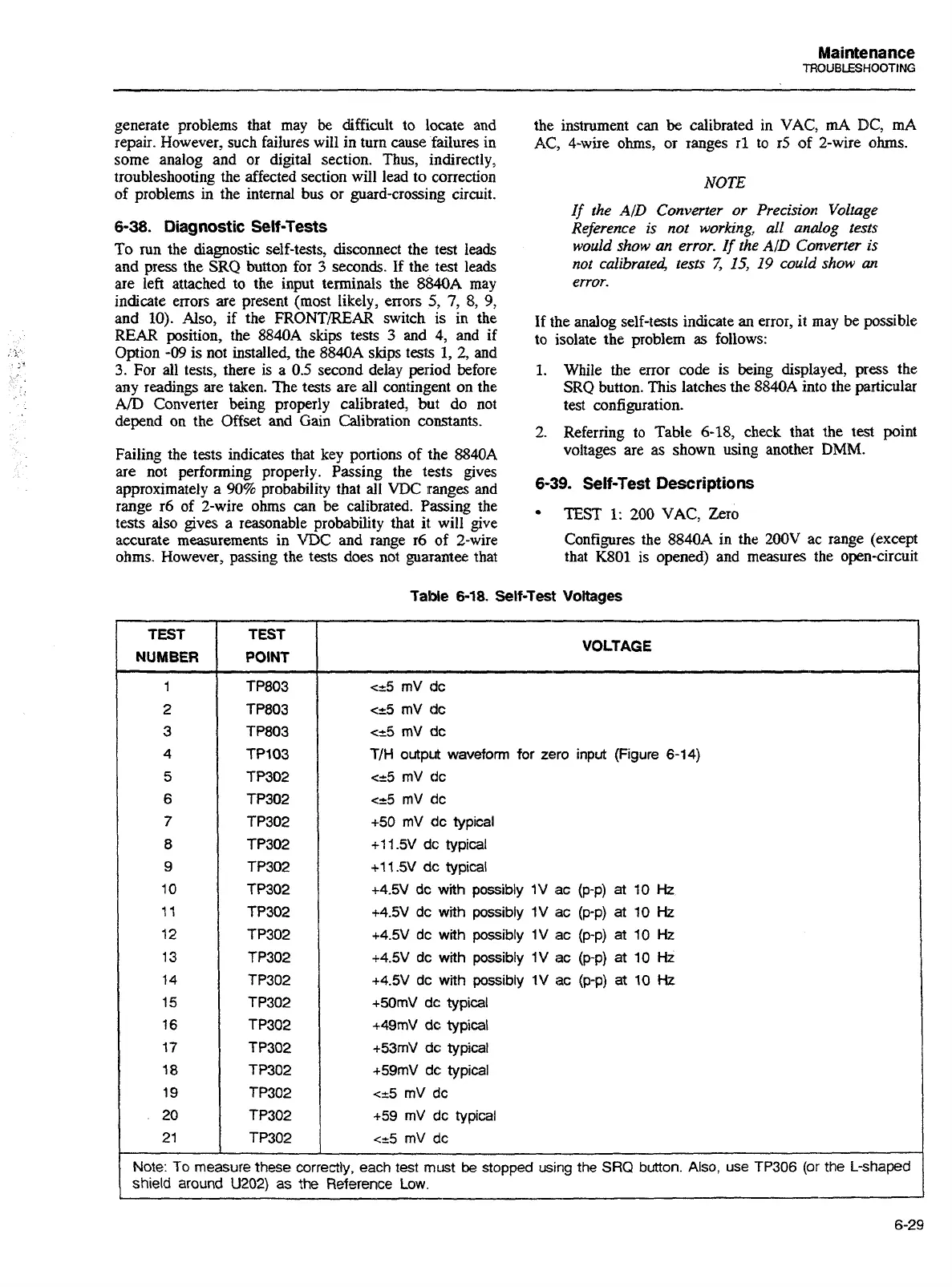
2.
Referring to Table 6-18, check that the test point
voltages are as shown using another
DMM.
6-39.
Self-Test Descriptions
TEST
1:
200
VAC, Zero
Configures the 8840A in the
200V
ac range (except
that K801 is opened) and measures the open-circuit
Table
6-18.
Self-lest
Voltages
VOLTAGE
<-.5 rnV dc
<=5
mV dc
<&I
mV dc
T/H
output
waveform for zero
input
(Figure 6-14)
<-5 mV dc
<=5
mV dc
+50 mV dc typical
+I
1.5V dc typical
+11.5V dc typical
+4.5V dc
with
possibly 1V
ac
(p-p)
at
10
Hz
+4.5V dc
with
possibly 1V
ac
(p-p)
at
10
Hz
+4.5V dc
with
possibly 1V ac (p-p)
at
10
Hz
+4.5V dc with possibly 1V ac (p-p)
at
10
Hz
+4.5V dc
with
possibly 1V ac
(p-p)
at
10
Hz
+50mV dc typical
+49mV dc typical
+53mV
dc:
typical
+59mV dc typical
~25 rnV dc
159 rnV dc typical
<t5
mV
dc
Note:
To
measure
these
correctly,
each
test
must
be
stopped
using
the
SRQ
button.
Also, use TP306
(or
the
L-shaped
shield around
U202)
as
the Reference
Low.
Artisan Technology Group - Quality Instrumentation ... Guaranteed | (888) 88-SOURCE | www.artisantg.com