Remote Programming
INPUr
SyNrAX
"F3
?
F4"
Correct construction. The'8840A is con-
figured in F3, and the trigger is executed.
Then the 884OA is left in
F4.
3-40.
OUTPUT
DATA
The following paragraphs describe the data that can be
loaded into the 8840A output buffer and sent to the
IEEE-488 bus. The paragraphs describe how and when
data is loaded into the output buffer, the types of output
data, and their relative priority.
Note that the
8WA
can
also send data to the IEEE-488
bus from the serial poll register. For a description of this
data,
see paragraph
3-50.
3-41.
Loading
Output Data
The output buffer is loaded when the 8840A receives
an
output command, or when an error occurs. Output com-
mands are those device-dependent commands which load
the output buffer with data:
Get commands
(GO
through G8)
Single-trigger command
(?)
Group execute trigger (GET)
Continuous Trigger
(TO)
Because the
8840A
gives priority to input processing, it
completely processes all characters in the input buffer
before it loads the output buffer. When the output buffer is
loaded, the Data Available bit
in
the
serial
poll
register is
set true.
Data from the output buffer is not actually loaded onto the
IEEE-488 bus until the controller addresses the
8840A
as
a
talker. This is done by sending the interface message
MTA
(My
Talk
Address).
342.
Types of
Output
Data
The types of data that
can
be loaded into the output buffer
are- shown in Figure 3-6. Each type has its own format.
Error messages, which are loaded into the output buffer if
an
error occurs, are formatted
as
numeric data.
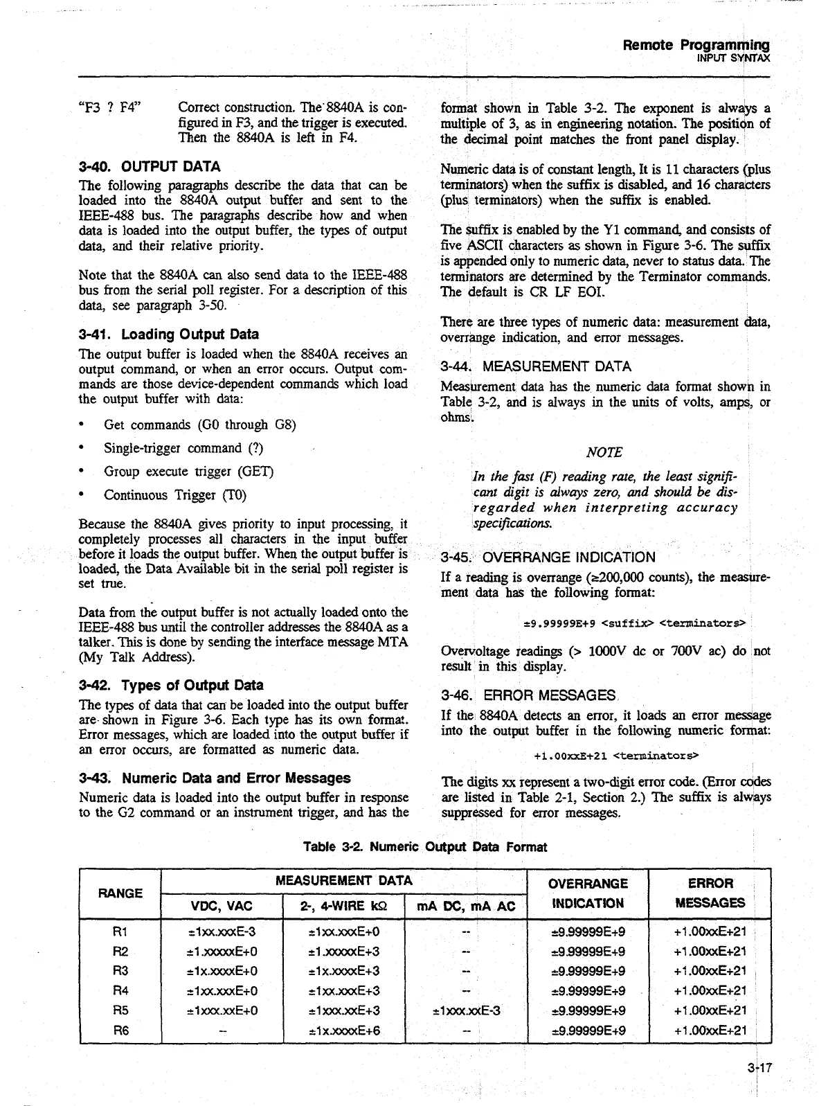
3-43.
Numeric Data
and
Error Messages
Numeric data is loaded into the output buffer in response
to the
G2
command
01
an
instrument trigger, and has the
1
RANEE
format shown in Table
3-2.
The exponent is always a
multiple of
3,
as
in engineering notation. The positiidn of
the decimal point matches the front panel display.
Numeric data is of constant length, It is
11
characters
@lus
terminators3 when the suffix
is
disabled, and
16
characters
(plus terminators) when the
suffi
is enabled.
The suffix is enabled by the
Y1
command, and consists of
five ASCII characters
as
shown in Figure
3-6.
The
$@fix
is appended only to numeric data, never to status data. The
terminators are determined by the Terminator commands.
The default is
CR
LF
EOI.
There are three types of numeric
data:
measurement
data,
overrange indication, and error messages.
3-44.
MEASUREMENT
DATA
Measurement data has the numeric data format showtl in
Table 3-2, and is always
in
the units of volts, amps, or
ohms.
NOTE
In the fast
(F)
reading rate,
the
leart signifi-
cant digit
is
always
zero,
and
should be dis-
regarded when interpreting accuracy
specifications.
3-45.
OVERRANGE INDICATION
If a reading is overrange
(r200,OOO
counts), the measure-
ment data
has
the following format:
Overvoltage readings
(>
lOOOV
dc or
700V
ac) do not
result
in
this display.
3-46.
ERROR MESSAGES
If
the 884OA detects
an
error, it loads an error message
into the output buffer in the following numeric format:
+1,00xxE+21
<terminatorY
The digits
xx
represent
a
two-digit error code. (Error ccrdes
are listed in Table 2-1, Section
2.)
The suffix is always
suppressed for error messages.
Table
3-2.
Numeric
Output
Data
Format
MEASUREMENT DATA
-
OVERRANGE
INDICATION
&.99999E+9
ERROR
MESSAGES
+I
.OOxxE+21
mA
DC,
mA
AC
--
VDC,
VAC
2-,
4-WIRE
kR
tl
xx.mE+O
Artisan Technology Group - Quality Instrumentation ... Guaranteed | (888) 88-SOURCE | www.artisantg.com