Theory
of
0
PRECISION
DAC
A/D AMPLlf IER
+7v
T
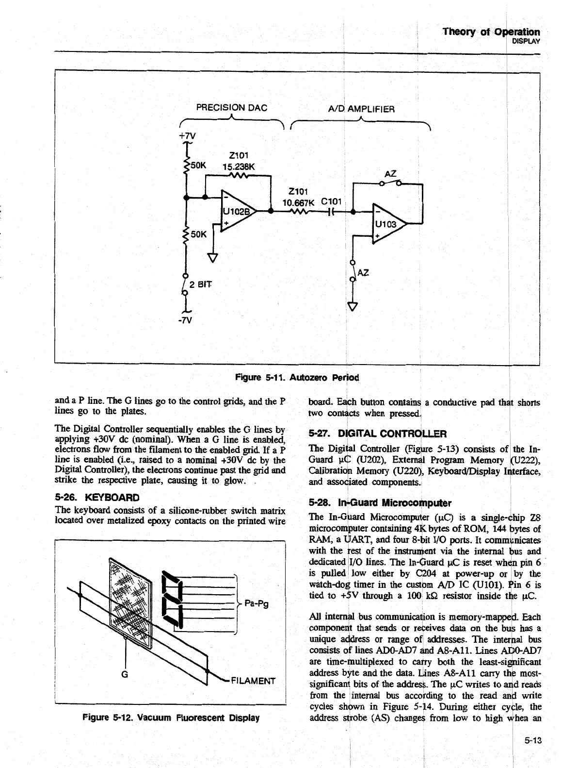
Fgure
5-1
1.
Autozero
Period
and a
P
line. The
G
lines go to the control
grids,
and the
P
board. F+h button contains a conductive pad th
lines go to the plates.
two cont&s when pressed.
The Digital Controller sequentially enables the
G
lines by
527.
DIGITAL
CONT~~R
applying
+30V
dc (nominal). When a
G
line
is
enabled,
electrons flow from the filament to the enabled grid. If a
P
The Digital Controller (Figure 5-13) ~~nsists
a
line is enabled (i.e., raised to a nominal +30V
dc
by the Guard
116
W202),
External Program Memory
Digital Controller), the electrons continue
past
the
grid
and
Calibratim Memory
(U220),
KeyboarVDisplay
I
strike the respective plate, causing it to glow.
and assoaiated components.
!ration
DISPLAY
-
shorts
he In-
u2221,
erface,
lip 28
ytes
of
~icates
is
and
I
pin
6
)y
the
n
6
is
:
PC.
.
Each
has
a
a1
bus
)-AD7
ificant
most-
l
reads
write
e, the
!en
an
5-1
3
5-26.
KEYBOARD
5-28.
IMuard
Microcodnputer
The keyboard consists of a silicone-rubber switch matrix
located over metalized epoxy contacts on the printed wire
The In-Ghard MicrocompuSer
(PC)
is a single-
microcomputer containing
48
bytes of
ROM,
144
I
Pa-Pg
!
i
'
WwiwmT
I
G
1
i
I
RAM,
a
UART,
and four 8-bit
110
ports.
It coma
with the test of the instrunient via the intemai
dedicated
110
lines. The In-Guard
PC
is reset wh
is pulled low either by
C204
at power-up or
watchdog timer in the custbm
AID
IC (U101).
tied to +$V through a
100
k&
resistor inside
1
All
intern# bus communicahion is memory-mapp
component that sends or receives data on the bi
unique address or range of addresses. The inte
consists of lines
ADO-AD7
and A8-All. Lines
A
are time-multiplexed to carry both the least-si
address byte and the data. Lines A8-All cany tl
significant bits of the addresb. The
pC
writes to a
from the internal bus according to the read
a~
cycles sh~wn in Figure
5-14.
During either
q
Figure
5-12.
Vacuum Fluorescent
Display
address strobe
(AS)
changes from low to high
Artisan Technology Group - Quality Instrumentation ... Guaranteed | (888) 88-SOURCE | www.artisantg.com