Theoty
of
Operation
AID
CONVERTER
D
AC
A/D
AMP
(x16)
f
A
+7v
2101 21 01
R105 15.2D8K
1 59.97K
50V
Sl
&
S2
I
I
BIT
SWITCHES SET
DURING PREVIOUS
COMPARE
PERIOD
-7v
"1,
0
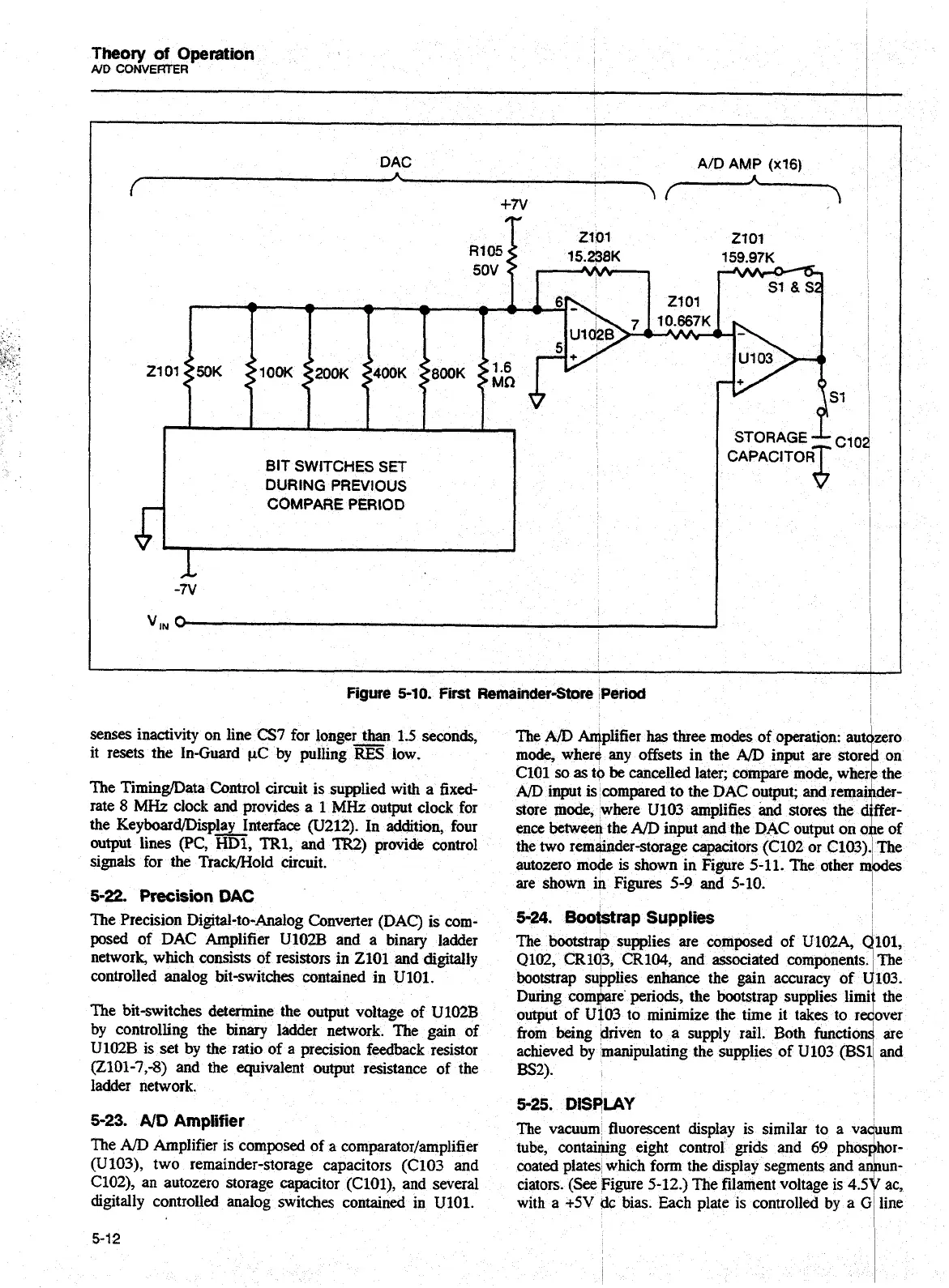
Figure
5-10.
First
Remainder-Store
Period
senses inactivity on line
CS7
for longer than 1.5 seconds,
The
A/D
Aqplifier
has
three modes of operation: aut
-
it resets the In-Guard
CLC
by pulling
RES
low.
mode, where any offsets in the
AD
input are storr
ClOl
so
as
tb
be
cancelled later; compare mode, whe.
The TiminglData Control circuit is supplied with a fixed-
AD
input iscompared to the DAC output; and remai
rate
8
MHz
clock and provides a
1
MHz
output clock for
store mode, where U103 amplifies and stores the
c
the Keyboard~Disp~nterface (U212). In addition, four
ence
betwee* the
AID
input and the DAC output on
c
output lines
(PC,
HD1,
TR1,
and
TR2)
provide control
the two remainder-storage capacitors (C102 or C103)
signals for the Track/Hold circuit.
autozero mode
is
shown in Figure 5-11. The other
n
are shown
in
Figures
5-9
and 5-10.
5-22.
Precision
DAC
The Precision Digital-to-Analog Converter
(DAC)
is corn-
5-24.
WM~P
Supplies
posed of DAC Amplifier U102B and a binary ladder
The bootstrap supplies are composed of
U102A,
(
network, which consists of resistors in 2101 and digitally
Q102, CR103, CR104, and associated components
controlled analog bit-switches contained in
U101.
bootstrap supplies enhance the gain accuracy of
1
During
compare
periods,
the bootstrap supplies lim
The bit-switches determine the output voltage of U102B
output of Ui03 to minimize the time it takes to re
by controlling the binary ladder network. The gain of
from
being driven to a supply rail. Both function
U102B is set by the ratio of a precision feedback resistor
achieved by manipulating the supplies of U103 (BS
(2101-7,-8) and the equivalent output resistance of the
BS2).
ladder network.
5-25.
DISPLAY
5-23.
ND
Amplifier
The vacuum fluorescent display is similar to a va
The
A/D
Amplifier is composed of a comparator/amplifier
tube, containing eight control grids and
69
phos
(U103), two remainder-storage capacitors (C103 and
coated plates which form the display segments and
a
C102), an autozero storage capacitor (ClOl), and several
ciators. (See Figure 5-12.) The filament voltage
is
4.5
digitally controlled analog switches contained in U101.
with
a
+5V
dc bias. Each plate is controlled by a
(
-
-
d
mo
on
the
der-
fer-
e
of
The
des
101,
The
103.
the
mr
are
and
lum
hor-
lun-
'
ac,
line
Artisan Technology Group - Quality Instrumentation ... Guaranteed | (888) 88-SOURCE | www.artisantg.com