Remote Programming
AN
OVERVIEW
OF
REMOTE
OPERATION
Information is transferred between blocks by device-
36.
DEVICE-DEPENDENT COMMAND
SET
-
dependent commands.
bCh
command is shown next to an
Devi=&pen&nt commands
are
the hem of
arrowhead which indicates the resulting information trans-
remote conBol. They tell the
the input buffer and stores it in the
primary
status
registers. make se~ce requests, etc. Cdmmands which cor
fer. For example, Put command
PO
takes a number from
make measurements, when to put data on the bus, whkn to
Likewise, Get command
GO
gets the content of the
pri-
directly to the
front
panel conthls or
display
are
mary
status
registers and copies it into the output buffer.
Figure 34. The complete
set
of device-depenht
man& is listed in Figure
3-5.
The
3-5.
A
NOTE
ABOUT
EXAMPLES
entered using either upper- or lower-case letters.
See
table
6-15 for conditions under whiuh certain cornman& de not
In the examples in this manual, device-dependent
com-
vdid.
marids are shown enclosed within quotation
marks,
as they
would
be
entered
in
Fluke BASIC. For clarity, the com-
Devicedependent commands are &.vice-&pendent me-
mads
are
also
separated by
spaces.
Hmever, the
SPm
sages.
For the
884OA
to receive them, they must
be/
sent
are are not necessary and may
be
omitted.
over the IEEE-488 bus when the
884OA
is
in
remote and
has
been
addressed
as
a
listmer.
Example Explanation
I
I
ONLY ONLY ONLY
"*
F3 R1 S1
T2"
This example is equivalent to
"*F3RlSl'I2" or "*,F3,Rl,Sl,V"'
?)
are described last.
00
01
02
03
04
05
06
07
08
09
10
Using the Fluke 172214 hstrurnent Controller, these com-
3-7.
Bn
(offset
Commands)
I
be
vniltra
into
a
pro@=
as
shown
me
Offset man& dupli~te the fundon of the
front
in
Figure 3-3. Examples using other controllers are given
omsFT
buaon.
when
the
MA
rccdva
de
~1
at the end of this section.
command, the
WA
stores the present reading
bs
an
offset for the present function. The BO command
8840A
Output
data
show
the
terminators
CR
the offset.
As
with
front panelloperaion, only one
and
LF.
The terminator EOI is not shown
because
it
is
a
allowed
at
a
time.
uniline message. However, the terminators
CR,
LF,
and
EOI
are all selectable using the Write commands.
The offset status (not the offget value)
can
be
the
G5
command. The 8840A defaults to
For reference, the ASCII and IEEE Std 488-1978 bus
power-up
and
on any device-clear command
(*,
codes are shown at the back of this section. SDC).
I
I
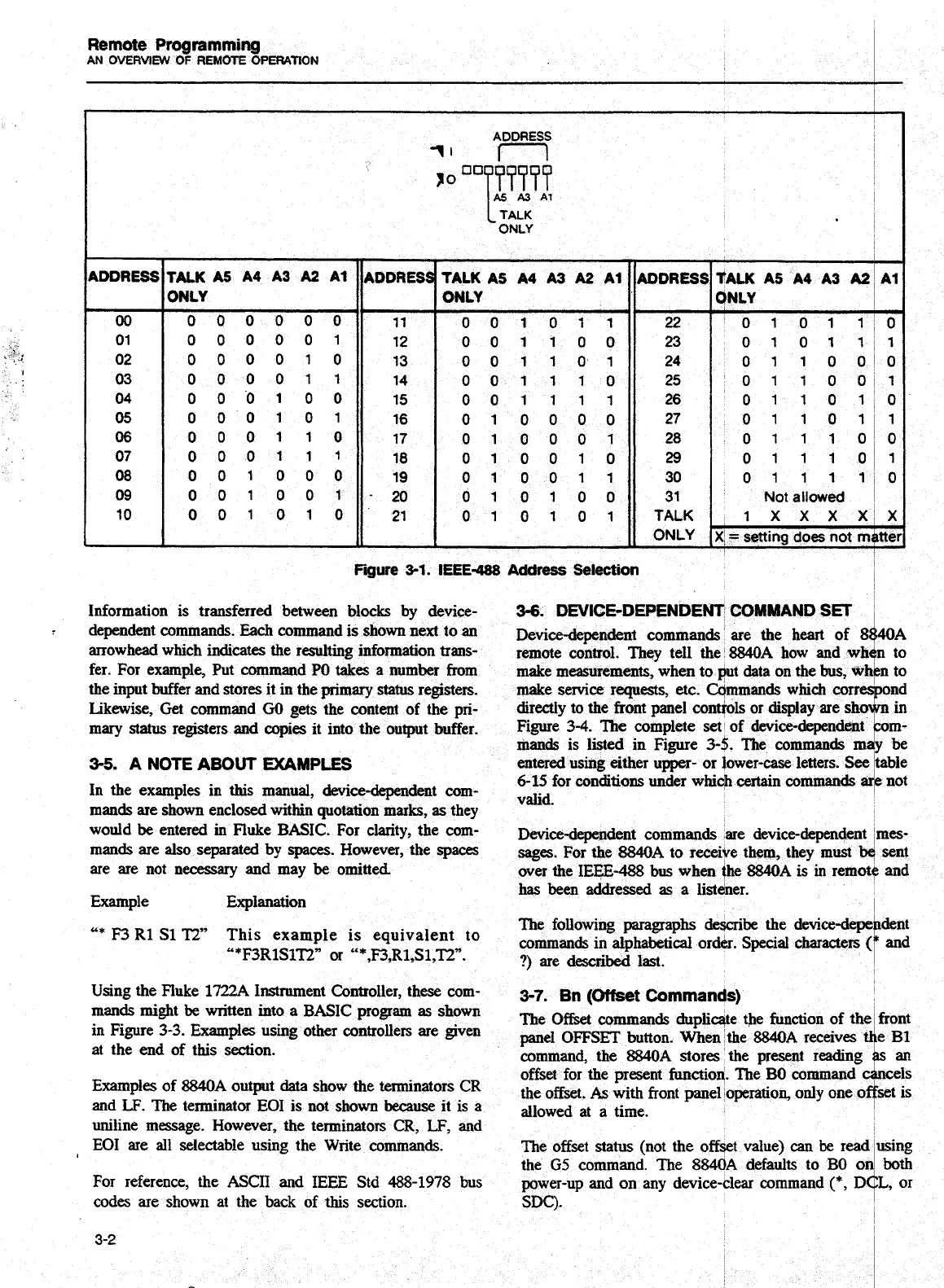
Fiure
3-1.
IEEE-488
Address
Selection
000000
000001
000010
000011
000100
000101
000110
000111
001000
001001
001010
11
12
13
14
15
16
17
18
19
-20
21
001011
001100
001101
001110
001111
010000
010001
010010
010011
010100
0 1
0
1 0 1
22
23
24
25
26
27
28
29
30
31
TALK
ONLY
0 10 1lIO
0 10 1
lll
0 11 0 010
0 11 0 011
0 11 0
lIO
0 11 0 111
01 11 010
0 11 1
O+
0 11 1110
Not
allowed
1
X
X
X
XIX
XI
I
=
setting does not
matter,
Artisan Technology Group - Quality Instrumentation ... Guaranteed | (888) 88-SOURCE | www.artisantg.com