Maintenance
TROUBLESHOOTING
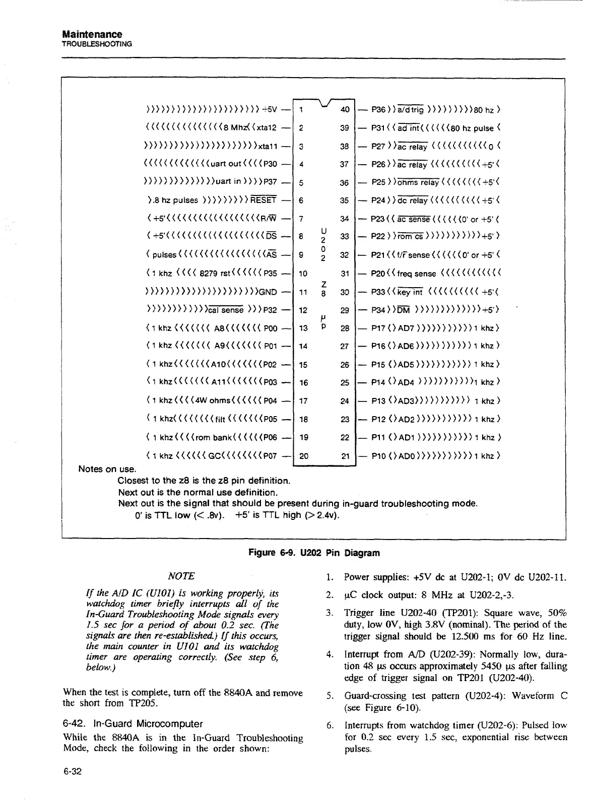
Closest to the
28
is the
28
pin definition.
Next out is the normal use definition.
Next out is the signal that should be present during in-guard troubleshooting mode.
I
i
0'
is
TTL
low
(<
.8v).
+5'
is
TTL
high
(>
2.4~).
Figure
6-9.
U202
Pin
Diagram
NOTE
If the
AID
IC
(UIOI)
is working properlj:
its
watchdog timer briepy interrupts
all
of
the
In-Guard Troubleshoofing Mode signals every
1.5
sec for a period of about
0.2
sec.
(The
signals are then re-established)
I/
this occu~s,
the main counter in
UIOI
and ils watchdog
timer are operating correctly. (See step
6,
below.)
When the test is complete, turn off the
8840A
and remove
the short from
TP205.
6-42.
In-Guard
Microcomputer
While the 8840A is
in
the In-Guard Troubleshooting
Mode, check the following in the order shown:
Power supplies:
t5V
dc at
U202-1;
OV
dc
U202-
11.
PC
clock output:
8
MHz at
U202-2,-3.
'Trigger line
U202-40 (TP201):
Square wave,
50%
duty, low
OV,
high
3.8V
(nominal).
The
period of the
trigger signal should
be
12.500
ms for
60
Hz
line.
Interrupt from
A/D
(U202-39):
Normally low, dura-
tion
48
ps
occurs approximately
5450
ps after falling
edge of trigger signal
on
TP201 (U202-40).
Guard-crossing test pattern
(U202-4):
Waveform
C
(see Figure
6-10).
Interrupts from watchdog timer
(U202-4):
Pulsed low
for
0.2
sec every
1.5
sec, exponential rise between
pulses.
Artisan Technology Group - Quality Instrumentation ... Guaranteed | (888) 88-SOURCE | www.artisantg.com