Operating Instructions
MAKING
MEASUREMENTS
I
2-26. Measuring
Vottage
and ~esi&nce
To measure voltage or resistance, select the desired func-
tion and connect the test leads
as
shown in Figure 2-9.
Resistance
can
be
measured in either the 2-wire or 4-wire
configuration.
2-27. Measuring
Current
To measure current, select the desired function and con-
nect the test lea&
as
follows:
Turn off power in the circuit to
be
measured (see
Figure 2-10).
Break the circuit (preferably on the ground side to
minimize the common mode voltage), and place the
8840A in series at that point.
Turn on power in the circuit, and read the display.
Turn off power in the circuit, and disconnect the
8840A.
2-28. Current Fuse
Protection
The
2A
input terminal is protected from overloads by a
2A,
250V
fuse which is accessible from the front panel,
and by an internal 3A,
600V
fuse. If either fuse blows, the
8840A
will respond as though the input were zero.
WARNING
TO AVOID ELECTRIC SHOCK, REMOVE
THE TEST
LEADS
BEFORE REPLACING
THE FRONT PANEL FUSE.
To replace the front panel
fuse,
first remove the test leads.
Then press in the lip of the
2A
input terminal slightly and
rotate
it
1/4-turn counterclockwise. Spring tension will
force the fuse and fuse holder out of the front panel. The
internal 3A fuse should
be
replaced only by qualified
service personnel.
2-29. Offset Measurements
WHEN THE OFFSET FEATURE IS IN
USE, DISPLAYED READINGS ARE
RELATIVE AND MAY NOT INDICATE
THE PRESENCE
qF DANGEROUS
POTENTIALS AT THE INPUT CONNEC-
TORS OR TEST
LEA&.
~JSE
CAUTION
TO AVOID ELECTRIC SHOCK OR
INSTRUMENT DAMAGE.
The OFFSET feature allows you to stare a reading
as
a
relative reference value. When the OFFSET button
is
pressed, the 8840A stores the present reading and disfilays
subsequent measurements
as
the difference betweed the
measured value and the stored reading. The
O~SET
annunciator is lit whenever
an
offset is in use.
The OFFSET feature may
be
used
in all functions. $ince
the display represents a numeric difference, it always
has
a
sign, even in the resistance and ac functions.
The offset can
be
cancelled by pressing the OFFSET
button again, in which
case
the OFFSET annunqiator
disappears from the display. The offset can also be
can-
celled by storing
an
offset in another function. If a reading
is overrange or unavailable when the OFFSET buttbn is
pressed,
the 8840A indicates ERROR
32
and do- not
store the offset.
If you change functions while an offset is storq the
OFFSET annunciator disappeats and the offset tempowily
disappears. However, when you return to the or@nal
function,
the
offset is restored (and the OFFSET annhcia-
tor reappears) unless a new offset was establish(td in
another function.
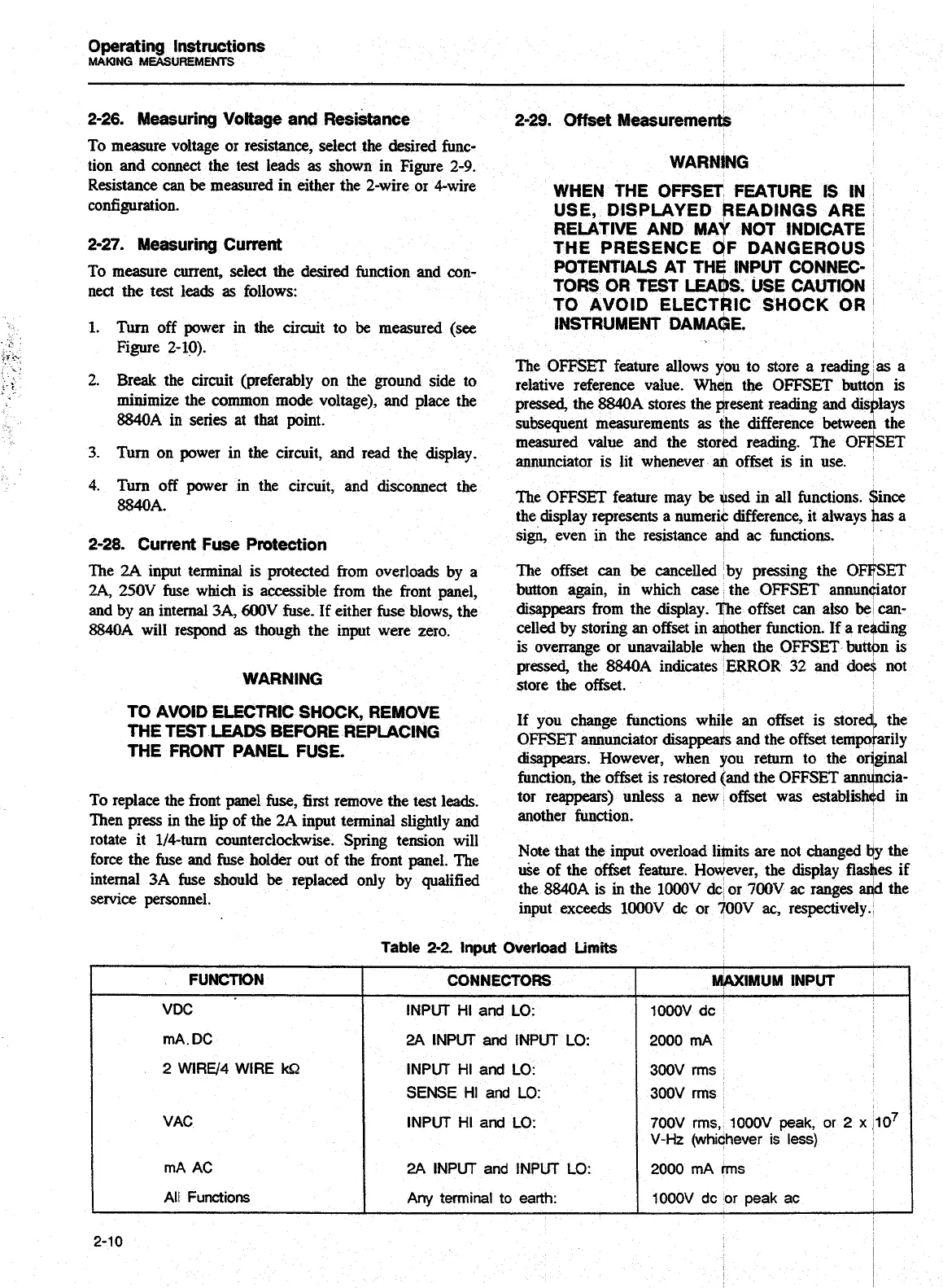
Note that the input overload limits are not changed
by
the
uie of the offset feature. However, the display flashes if
the 8840A is
in
the
lOOOV
&
or
700V
ac ranges aqd the
input exceeds
lOOOV
dc or 700V
ac,
respectively.
2A
INPUT and INPUT
LO:
2
WIRE/4 WIRE
W1
INPUT HI and
LO:
SENSE
HI
and
LO:
INPUT HI and
LO:
I
rnA
AC
I
2A
INPUT and INPUT
LO:
I
2000
mA
rrns
I
All
Functions
Any
terminal
to
earth:
lOOOV
dc
or
peak
ac
Artisan Technology Group - Quality Instrumentation ... Guaranteed | (888) 88-SOURCE | www.artisantg.com