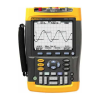
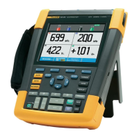
Fluke 190-062, -102, -104, -202, -204, -502, -504
Service Manual
5-30
6. Wait until the display shows calibration status :READY.
7. Press
F2
to select the next calibration step, set the 5502A to the next
calibration point signal, and start the calibration.
Continue through all calibration points of Table 5-9 and Table 5-10.
8. When you are finished, set the 5502A to Standby.
9. Continue at the Input B LF-HF Gain section.
Table 5-9. Input A LF-HF Gain Calibration Points
Cal step UUT input signal 5502A Setting
CL 0654 0.5 Vpp square wave, 1 kHz SCOPE edge, 0.5 Vpp, 1 kHz
CL 0480 0.62 Vpp sine wave, 50 kHz SCOPE levsine, 0.62 Vpp, 50 kHz
CL 0481 0.62 Vpp sine wave
Fluke 190-202/204: 221 MHz
Fluke 190-102: 151 MHz
Fluke 190-104: 121 MHz
Fluke 190-062: 81 MHz
SCOPE levsine, 0.62 Vpp,
221 MHz
151 MHz
121 MHz
81 MHz
Table 5-10. Input A LF-HF Gain Calibration Points (Extra steps for 190-104/204, V10.4x firmware *)
Cal step UUT input signal 5502A Setting
CL 0460 124 mVpp sine wave, 50 kHz SCOPE levsine, 124 mVpp, 50 kHz
CL 0461 124 mVpp sine wave
Fluke 190-204: 221 MHz
Fluke 190-104: 121 MHz
SCOPE levsine, 124 mVpp,
221 MHz
121 MHz
* Four channel instruments (190-104/204) with firmware V10.4x require the extra steps CL 460 and CL 461. Installed
firmware version can be checked via key sequence: USER key, F3 – VERSION & CAL, Software Version …
Artisan Technology Group - Quality Instrumentation ... Guaranteed | (888) 88-SOURCE | www.artisantg.com

 Loading...


