Calibration Adjustment
Final Calibration (Firmware: V10.9 and Lower) 5
5-29
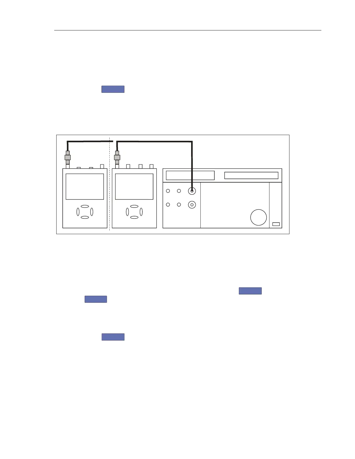
4. Connect the Test Tool to the 5502A SCOPE output as shown in Figure 5-11.
Use the 50 Ω termination.
5. Set the 5502A to generate a sine wave 50 MHz / 0.5 V pp (mode LEVSINE)
at the SCOPE output.
6. Set the 5502A to operate (OPR).
7. Press
F3
to start the calibration.
8. Wait until the display shows calibration status
:READY.
9. Set the 5502A to standby (STBY).
10. Continue at the Input A LF-HF Gain section.
NORMAL
SCOPE
FLUKE 5502A CALIBRATOR
PM9091
ADC
B
50 OHM e.g. PM9585 or
TRM50
USE 50 OHM
TERMINATION
AB
METER
50 OHM e.g. PM9585 or
TRM50
For 190-502 and -504 only
use TRM50!
PM9091
2 CHANN. + METER
4 CHANNELS
Perf-Ver-D2.eps
Figure 5-11. 5502A SCOPE Output to Test Tool Input A
Input A LF-HF Gain
To do the Input A LF-HF Gain calibration:
1. Connect the Test Tool to the 5502A as shown in Figure 5-11.
2. The display must show step CL 0654. If it does not, press
F2
or
F1
to select the first calibration step in Table 5-9.
3. Set the 5502A SCOPE output to source the signal required for the first
calibration point in Table 5-9.
4. Set the 5502A to operate (OPR) or standby (STBY) as indicated.
5. Press
F3
to start the calibration.
Artisan Technology Group - Quality Instrumentation ... Guaranteed | (888) 88-SOURCE | www.artisantg.com
 Loading...


