Fluke 190-062, -102, -104, -202, -204, -502, -504
Service Manual
5-14
Input B LF-HF Gain
To do the Input B LF-HF Gain calibration:
1. Press
F2
to select the first calibration step in Table 5-2.
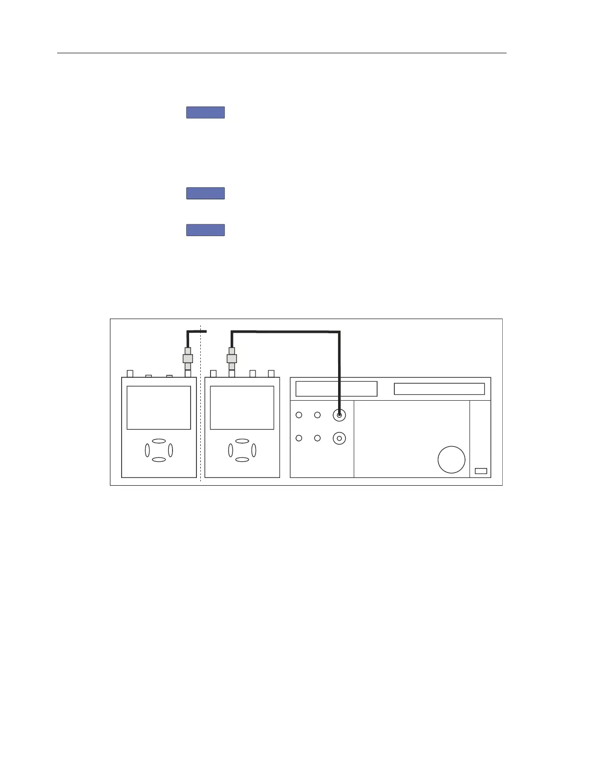
2. Connect Ch. B of the Test Tool to the 5502A as shown in Figure 5-4.
3. Set the 5502A SCOPE output to source the signal required for the first
calibration point in Table 5-2 (CL 0674, Pos B Fast).
4. Set the 5502A to operate (OPR) or standby (STBY) as indicated.
5. Press
F3
to start the calibration.
6. Wait until the display shows calibration status
:READY.
7. Press
F2
to select the next calibration step, set the 5502A to the next
calibration point signal, and start the calibration.
Continue through all calibration points of Table 5-2.
8. When you are finished, set the 5502A to Standby.
9. Continue at the Input C LF-HF Gain section.
NORMAL
SCOPE
FLUKE 5502A CALIBRATOR
PM9091
ADC
B
USE 50 OHM
TERMINATION
AB
METER
PM9091
2 CHANN. + METER
4 CHANNELS
50 OHM e.g. PM9585 or
TRM50
For 190-502 and -504
use only TRM50!
50 OHM e.g. PM9585 or
TRM50
Perf-Ver-E2.eps
Figure 5-4. 5502A SCOPE Output to Test Tool Input B
Artisan Technology Group - Quality Instrumentation ... Guaranteed | (888) 88-SOURCE | www.artisantg.com
 Loading...


