Fluke 190-062, -102, -104, -202, -204, -502, -504
Service Manual
4-26
6. When you are finished, set the 5502A to Standby.
Table 4-12. HF AC Voltage Verification Points
UUT
Model
5502A SC... MODE levsine
UUT
Reading B
Voltage Frequency
All 2.545 Vpp 1 MHz 835 mV to 965 mV
All 2.545 Vpp 25 MHz 790 mV to 1.010 V
190-062 2.545 Vpp 60 MHz >630 mV
190-104, -102 2.545 Vpp 100 MHz >630 mV
190-204, -202 2.545 Vpp 200 MHz >630 mV
190-502; -504 2.545 Vpp 500 MHz >630 mV
Input C Trigger Sensitivity Test
Note
The test steps for channel C are only for the models 190-104,
190-204, and 190-504.
Proceed as follows to test the Input C trigger sensitivity:
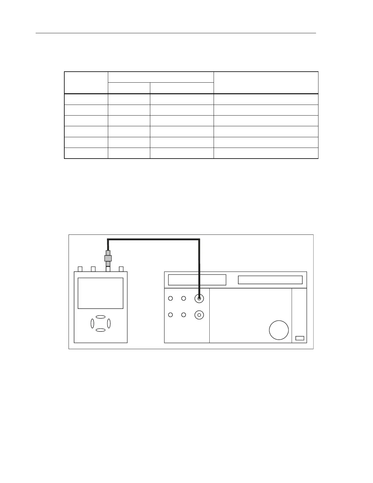
1. Connect the Test Tool to the 5502A as shown in Figure 4-9.
ADC
B
NORMAL
SCOPE
FLUKE 5502A CALIBRATOR
PM9091
PM9585 - 50 OHM
USE 50 OHM
TERMINATION
4 CHANNELS
For 190-502 and -504
use only TRM50!
perf-ver-f2.eps
Figure 4-9. 5502A Scope Output to Test Tool Input C
Artisan Technology Group - Quality Instrumentation ... Guaranteed | (888) 88-SOURCE | www.artisantg.com
 Loading...


