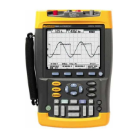
Fluke 190-062, -102, -104, -202, -204, -502, -504
Service Manual
4-20
5. Set the 5502A to source a sine wave according to the first test point in
Table 4-8.
Because no 50 Ω termination is applied, the 5502A leveled sine wave output
amplitude will be twice the set value.
6. Observe the readings
A, B, C, and D and check that they are not outside the
range shown under the appropriate column.
7. Continue through the test points.
8. When you are finished, set the 5502A to 0 (zero) Volt and Standby.
Table 4-8. Phase Measurement Verification Points
Time base 5502A-SC... MODE Frequency Voltage
Input A, B, C, D
Reading … Deg
20 ms/div wavegen, sine, 1 MΩ 10 Hz 600 mVpp -2 to +2
200 ns/div levsine 1 MHz 300 mVpp -2 to +2
20 ns/div levsine 10 MHz 300 mVpp -3 to +3
Time Base Test
Proceed as follows to test the time base accuracy:
1. Connect the Test Tool to the 5502A as shown in Figure 4-6.
For the Fluke 190-502 and 190-504 you must use the Fluke TRM50 50 Ω
terminator.
NORMAL
SCOPE
FLUKE 5502A CALIBRATOR
PM9091
ADC
B
50 OHM e.g. PM9585 or
TRM50
USE 50 OHM
TERMINATION
AB
METER
50 OHM e.g. PM9585 or
TRM50
For 190-502 and -504 only
use TRM50!
PM9091
2 CHANN. + METER
4 CHANNELS
perf-ver-d2.eps
Figure 4-6. 5502A Scope Output to Test Tool Input A
2. Set the 5502A to source an 8 ms time marker (MODE marker).
Artisan Technology Group - Quality Instrumentation ... Guaranteed | (888) 88-SOURCE | www.artisantg.com

 Loading...


