Fluke 190-062, -102, -104, -202, -204, -502, -504
Service Manual
5-38
Input ABCD (AB) Position
To do the Input ABCD (AB) Position calibration:
1. Press
F2
to select calibration adjustment step CL 0619.
2. Remove all Input A, B, C, D (A, B) connections (open inputs).
3. Press
F3
to start the calibration.
4. Wait until the display shows calibration status
:READY.
5. Continue at the Input ABCD (AB) Volt Gain section.
Input ABCD (AB) Volt Gain
Warning
To prevent possible electrical shock, fire, or personal injury,
ensure that the calibrator is in standby mode before making any
connection between the calibrator and the Test Tool.
Dangerous voltages are present on the calibration source and
connection cables during these steps.
Note
The adjustment steps for channel C and D are only for the models
190-104 and 190-204.
To do the Input ABCD (AB) Volt Gain calibration:
1. Press
F2
to select the first calibration step in Table 5-18.
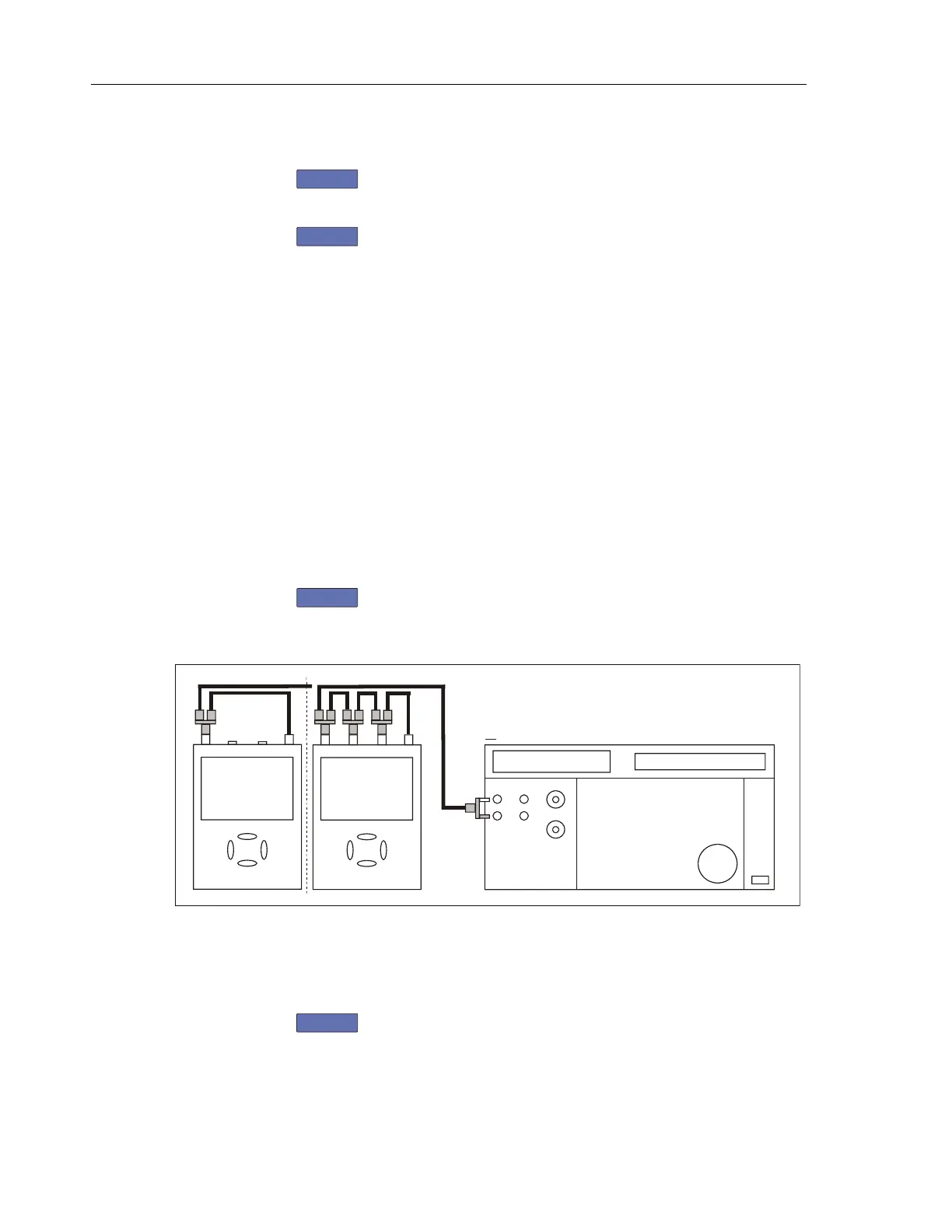
2. Connect the Test Tool to the 5502A as shown in Figure 5-16.
NORMAL SCOPE
FLUKE 5502A CALIBRATOR
PM9091
PM9081
CONNECT TO CHANNEL A, B, C, D IN PARALLEL
50 OHM TERMINATIONNO
ADC
B
PM9093
PM9092
AB
METER
P
M
9
0
9
3
PM9092
2 CHANN. + METER
4 CHANNELS
Figure 5-16. Test Tool Input ABCD to 5502A Normal Output
3. Set the 5502A to supply a DC voltage (NORMAL output) to the first
calibration point in Table 5-18.
4. Set the 5502A to operate (OPR).
5. Press
F3
to start the calibration.
6. Wait until the display shows calibration status
:READY.
Artisan Technology Group - Quality Instrumentation ... Guaranteed | (888) 88-SOURCE | www.artisantg.com
 Loading...


