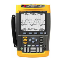
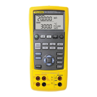
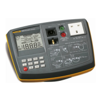
Fluke-062, -102, -104, -202, -204, -502, -504
Service Manual
ii
Scope Input A, B, C, D Tests ........................................................................... 4-8
Input A, B, C, D Vertical Accuracy Test ....................................................... 4-8
Input A, B, C, D DC Voltage Accuracy Test ................................................. 4-11
Input A, B, C, D AC Voltage Accuracy Test (LF) .......................................... 4-14
Input A, B, C, D AC-Coupled Lower Frequency Test ................................... 4-16
Input A, B, C, D Peak Measurements Test .................................................. 4-17
Input A, B, C, D Frequency Measurement Accuracy Test ............................ 4-18
Input A&B / C&D Phase Measurements Test .............................................. 4-19
Time Base Test ........................................................................................... 4-20
Input A Trigger Sensitivity Test .................................................................... 4-21
Input A AC Voltage Accuracy (HF) and Bandwidth Test .............................. 4-23
Input B Trigger Sensitivity Test .................................................................... 4-24
Input B AC Voltage Accuracy (HF) and Bandwidth Test .............................. 4-25
Input C Trigger Sensitivity Test .................................................................... 4-26
Input C AC Voltage Accuracy (HF) and Bandwidth Test .............................. 4-27
Input D Trigger Sensitivity Test .................................................................... 4-28
Input D AC Voltage Accuracy (HF) and Bandwidth Test .............................. 4-30
Video Test with SC600 Scope Calibration Option ........................................ 4-31
External Trigger Level Test .............................................................................. 4-34
Meter Tests ...................................................................................................... 4-35
Meter DC Voltage Accuracy Test ................................................................. 4-35
Meter AC Voltage Accuracy and Frequency Response Test ....................... 4-36
Continuity Function Test .............................................................................. 4-37
Diode Test Function Test ............................................................................. 4-37
Ohms Measurements Test .......................................................................... 4-38
Probe Calibration Generator Test ................................................................ 4-39
5 Calibration Adjustment ..................................................................................... 5-1
Introduction ...................................................................................................... 5-3
General ............................................................................................................ 5-4
Calibration Number and Date ...................................................................... 5-4
General Instructions ..................................................................................... 5-4
Equipment Required For Calibration ............................................................ 5-5
Calibration Procedure Steps ............................................................................ 5-5
How to Start the Calibration ............................................................................. 5-6
Contrast Calibration Adjustment ...................................................................... 5-7
Warming-Up and Pre-Calibration ..................................................................... 5-9
Final Calibration For v11.10 and later .............................................................. 5-10
Warming-Up 2, Warm-Up Final, and ADC Timing ........................................ 5-11
Input A LF-HF Gain ..................................................................................... 5-12
Input B LF-HF Gain ..................................................................................... 5-14
Input C LF-HF Gain ..................................................................................... 5-16
Input D LF-HF Gain ..................................................................................... 5-18
Input AB Position ......................................................................................... 5-20
Input AB LF-HF Gain and Position ............................................................... 5-20
Input Pos ABCD (AB) Calibration ................................................................ 5-22
Input ABCD (AB) Noise F FBW Calibration ................................................. 5-22
Input AB Volt Gain ....................................................................................... 5-22
Multimeter Meter Zero ................................................................................. 5-24
Multimeter Volt Gain .................................................................................... 5-24
Multimeter Ohm Gain ................................................................................... 5-26
Artisan Technology Group - Quality Instrumentation ... Guaranteed | (888) 88-SOURCE | www.artisantg.com

 Loading...


