Performance Verification
Scope Input A, B, C, D Tests 4
4-9
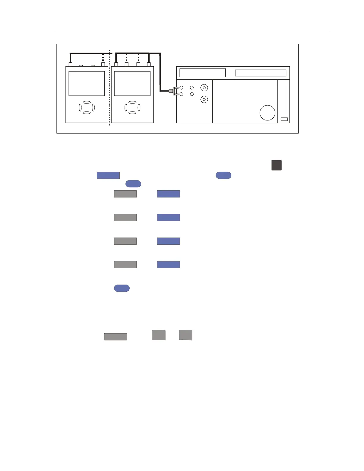
NORMAL SCOPE
FLUKE 5502A CALIBRATOR
ADC
B
PM9091
PM9081
CONNECT TO CHANNEL A, B, C, D IN SUCCESSION
50 OHM TERMINATIONNO
AB
METER
PM9091
2 CHANN. + METER
4 CHANNELS
perf-ver-a2.eps
Figure 4-3. Test Tool Inputs A, B to 5502A Normal Output
2. Select the following Test Tool setup:
a) Recall the created setup (see Standard Test Tool Setup). Press
SAVE
,
F2
(RECALL) and select SETUP, press
ENTER
, select the setup name,
and press
ENTER
to recall the setup.
b) Press
, press
F4
(INPUT A OPTIONS...), and select
Attenuator: Normal | Bandwidth: 10 kHz or 20 kHz for the available setting in
the Test Tool.
c) Press
B
, press
F4
(INPUT B OPTIONS...), and select
Attenuator: Normal | Bandwidth: 10 kHz or 20 kHz for the available setting in
the Test Tool.
d) Press
C
, press
F4
(INPUT C OPTIONS...), and select
Attenuator: Normal | Bandwidth: 10 kHz or 20 kHz for the available setting in
the Test Tool.
e) Press
D
, press
F4
(INPUT D OPTIONS...), and select
Attenuator: Normal | Bandwidth: 10 kHz or 20 kHz for the available setting in
the Test Tool.
f) Press
CLEAR
to clear the softkey menu and see the full display.
Note
The 10 kHz or 20 kHz bandwidth limiter rejects calibrator
noise. It does not affect the gain accuracy at a 50 Hz input
signal.
3. Press
and use
mV
RANGE
and
RANGE
to set the Input A sensitivity range to
the first test point in Table 4-2.
4. Set the 5502A to source the appropriate initial ac voltage.
5. Adjust the 5502A output voltage until the displayed Input A trace amplitude is
6 divisions.
6. Observe the 5502A output voltage and check to see if it is within the range
shown under the appropriate column.
7. Continue through the test points.
Artisan Technology Group - Quality Instrumentation ... Guaranteed | (888) 88-SOURCE | www.artisantg.com
 Loading...


