Locking
assembly:
Action:
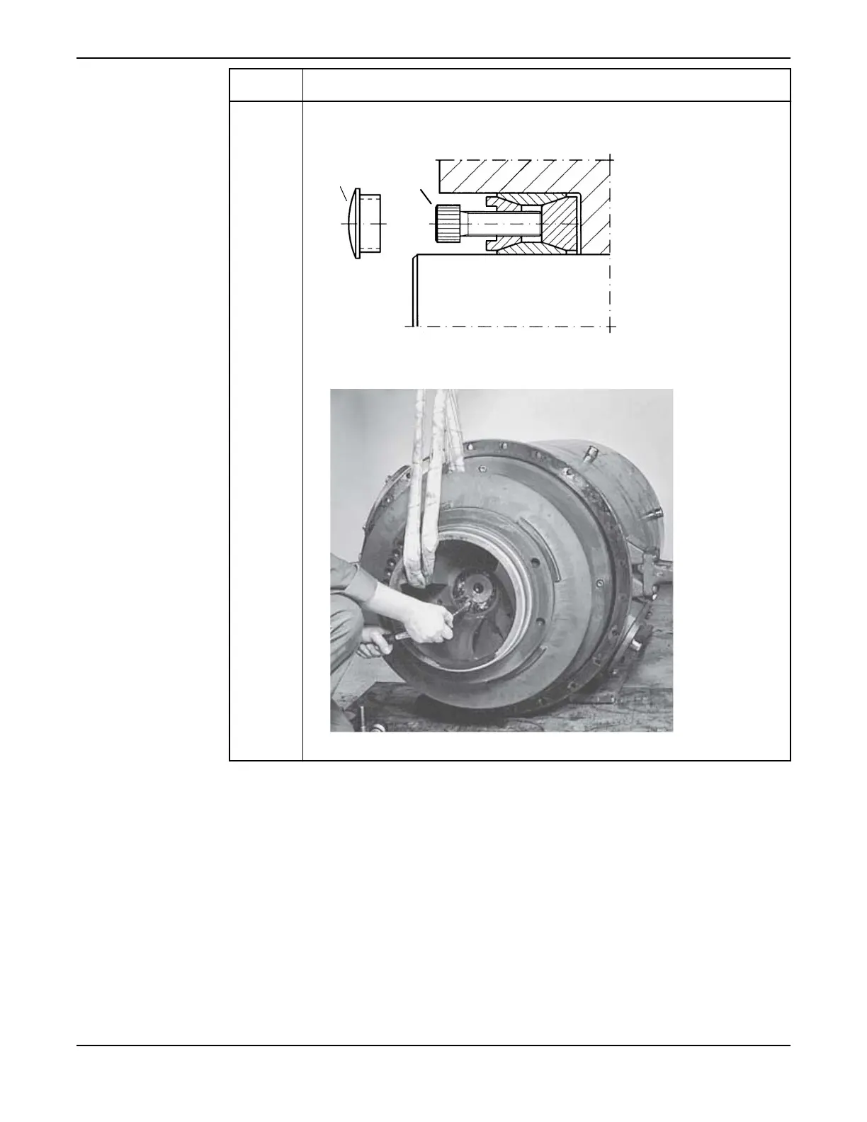
• 84 60 11 1. Remove the four plastic plugs (labelled “1” in figure below) covering the threaded
holes for the special separation screws.
2. Loosen the inner ring by means of four locking assembly screws (M14) as
separation screws (labelled “2” in figure above). See illustration below.
3. Remove the locking assembly.
2. Pull off the impeller:
a) Fit the tools required for impeller removal according to the tool list for the appropriate pump. See
Tools (page 102).
b) Pull off the impeller.
Use the hydraulic unit with the partially threaded screw in the Basic kits for removal (or screw unit
602 31 00 for C3800).
Maintenance
96 C3300/6x5, C/R3231, C3240, C3306, C3312, C3351, C3356, C3400, C3501, C3531, C3602, C3800 Installation,
Operation and Maintenance Manual