Locking
assembly:
Action:
• 84 59 12
• 84 59 13
• 84 59 14
• 84 59 17
1. Loosen the screws on the locking assembly evenly and in sequence. See Sequence for
tightening or loosening locking assembly bolts (page 99).
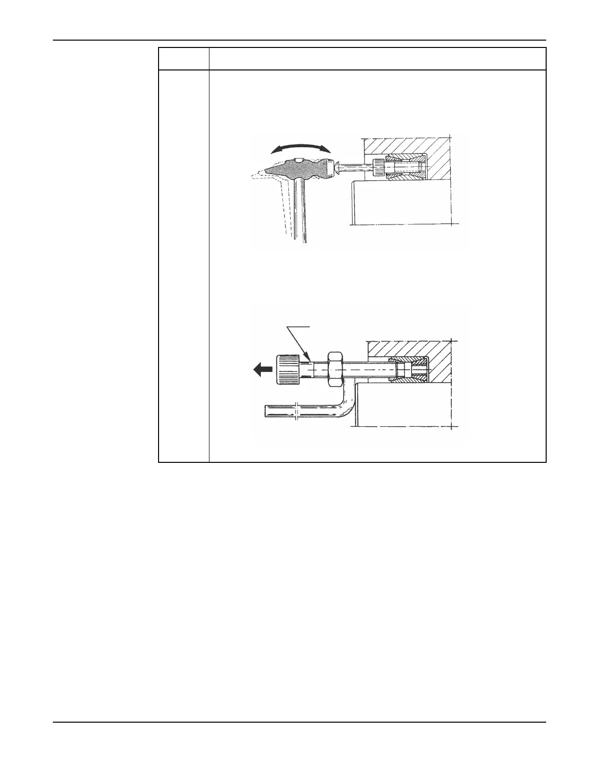
If the locking assembly is still locked, do as follows:
a. Loosen the inner ring by tapping it lightly, as shown in the illustration.
b. If tapping did not loosen the ring, replace the three "light-colored" screws
with three M10 draw-bolts (for 84 59 12 and 84 59 13) or M12 draw-bolts (for
84 59 14 and 84 59 17).
2. Remove the locking assembly.
Maintenance
C3300/6x5, C/R3231, C3240, C3306, C3312, C3351, C3356, C3400, C3501, C3531, C3602, C3800 Installation,
Operation and Maintenance Manual
95