36
4-1-12-1. GPI Input
1. Select a Unit number to save settings in Unit and select MFR-GPI unit ID for ID.
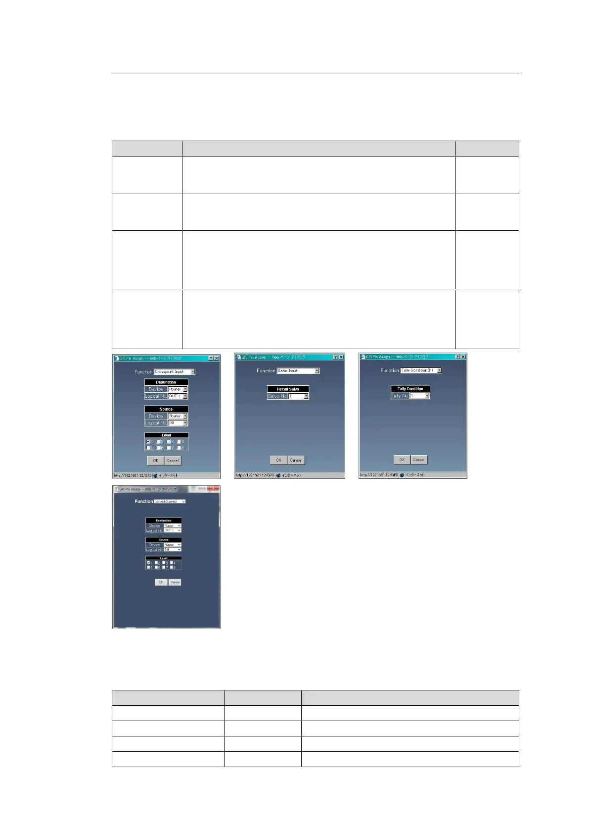
2. Click the Pin No. button. A setting dialog appears.
3. Select the pin function in Function. The screen changes according to the selected
function. Set the required settings and click the OK button.
When an input signal is enabled, a crosspoint switch is
performed according to the settings specified in this dialog
box.
When an input signal is enabled, an MU Salvo is performed.
Select the Salvo number specified in the Salvo page (see
Sec. 4-1-6), from 1 to 100.
When an input signal is enabled, the tally color set by Tally
No. becomes enabled. Enabling the input signal again
disables the tally color. Select the Tally No. from the
numbers set in Sec. 4-2-1 .“Assign Tally.” (Not supported by
MFR-1000.)
While an input is enabled, the router crosspoint is switched.
When input is disabled, the router crosspoint switches back.
If the switching interval is too short, the action is cancelled. In
such case, selecting Joystick Override allows you to select a
source. (MFR-3000/5000/8000 units only)
4. Set conditions for Edge/Level and Logical to recognize input as valid. When “Crosspoint
Input”, “Salvo Input” or “Joystick Override” is selected for Function, set Edge/Level
according to the table in Step 3.
Input is recognized as effective at a rising edge.
Input is recognized as effective at a falling edge.
Input becomes effective during HIGH.
Input becomes effective during LOW.