37
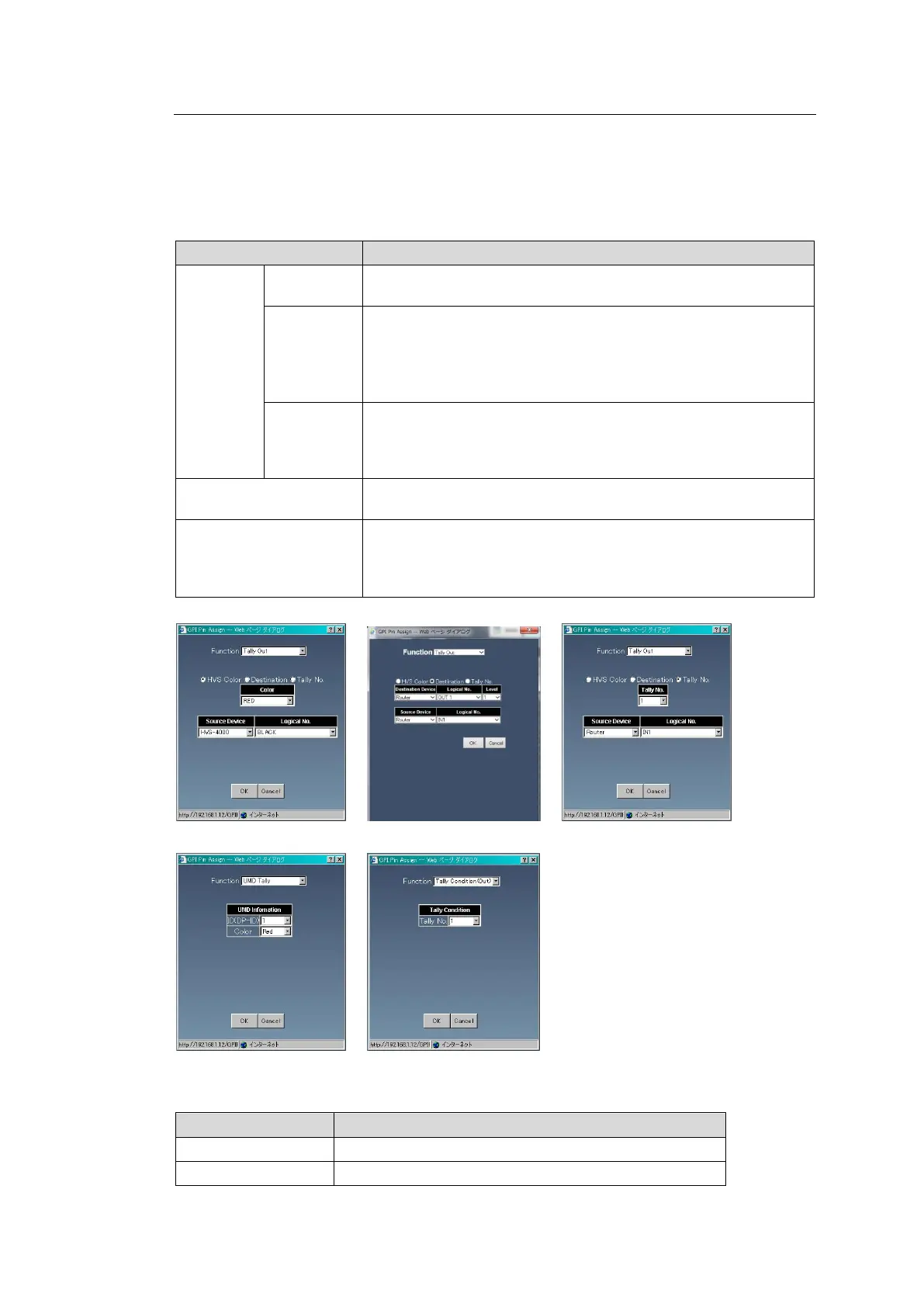
4-1-12-2. GPI Output
1. Select Unit No. to save settings and select MFR GPI Unit ID to apply.
2. Click the Pin No. button. A setting dialog appears.
3. Select the pin function from the Function column. The screen changes according to the
selected function. Set required settings and click OK. (MFR-1000: Only Tally Out
(Destination) is selectable)
Output becomes valid when the signal set by Source Device
and Logical No. becomes the color set by Color.
Output becomes valid when the destination set by Destination
Device, Logical No. and Level selects a source set by Source
Device and Logical No.
(MFR-1000: Destination Device and Source Device is fixed to
Router.)
Output becomes valid when the signal set by Source Device
and Logical No. becomes the tally color set by Tally No.
Tally Nos. are selected from numbers set by Sec. 4-2-1. “Assign
Tally.”
Output becomes valid when the tally color set by ID (DP-ID) and
Color turns on.
Output becomes valid when the tally color set by Tally No.
becomes valid.
Tally Nos. are selected from numbers set by Sec.4-2-1. “Assign
Tally.”
4. Set conditions for Logical to recognize output as valid.
Logical setting becomes HIGH when output is valid.
Logical setting becomes LOW when output is valid.