21
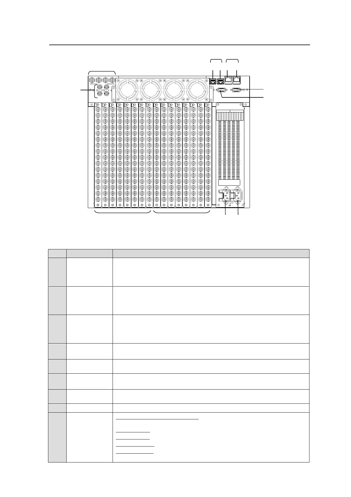
2-2. MFR-5000 Rear Panel
* The above figure shows an MFR-5000 with MFR-16SDI/16SDIA and MFR-16SDO cards
installed.
Ethernet ports for connection to MFR Remote Control Units and MFR-GPI
(10/100/1000BASE-T, RJ-45)
(1) For CPU 1
(2) For CPU 2
Ethernet ports for connection to PC or other external unit
(10/100BASE-TX RJ-45)
(1) For CPU 1
(2) For CPU 2
Used for control via a serial interface. RS-232C or RS-422 selectable.
► See section 2-2-1. "Interfaces."
The SERIAL connector is set to RS-232C as factory default. Consult your
FOR-A reseller if you wish to change the setting.
Used for alarm output
► See section 2-2-1. "Interfaces."
Used for monitor outputs (No automatic reclocking)
Used to input reference signals (BB or Tri-level sync signal)
(with loop-through. Terminate with 75Ω terminator, if unused.)
Used to connect Power Supply Unit 1 (standard equipment) to an AC
power source
Used to connect Power Supply Unit 2 (optional) to an AC power source
MFR-16SDI/16SDIA/16SDIGB: Used to input digital component video
signals
MFR-16ADI: Used to input digital audio signals
MFR-16AAI: Used to input analog audio signals
MFR-16AAIEX: Used to input analog audio signals
MFR-16AESI: Used to input digital audio signals
► See section 2-4. "Audio Input/Output Cards."
1 2 3 4
MONITOR OUT (SDI)
1 2
REF IN
SLOT
SERIALALARM
PC-LAN
(CPU2) (CPU1)(CPU2)(CPU1)
MFR -LAN
3G/HD/SD-SDI INPUT 3G/HD/SD-SDI OUTPUT
1 2 3 4 5 6 7 8 1 2 3 4 5 6 7 8
Rating Label
2
A
C
1
0
0
-
2
4
0
V
5
0
/
6
0
H
z
I
N
A
C
1
0
0
-
2
4
0
V
5
0
/
6
0
H
z
I
N
1
16
15
14
13
12
11
10
9
8
5
4
1
6
7
IN
1
3
2
16
15
14
13
12
11
10
9
8
5
4
1
6
7
IN
2
3
2
16
15
14
13
12
11
10
9
8
5
4
1
6
7
IN
3
3
2
16
15
14
13
12
11
10
9
8
5
4
1
6
7
IN
4
3
2
16
15
14
13
12
11
10
9
8
5
4
1
6
7
IN
5
3
2
16
15
14
13
12
11
10
9
8
5
4
1
6
7
IN
6
3
2
16
15
14
13
12
11
10
9
8
5
4
1
6
7
IN
7
3
2
16
15
14
13
12
11
10
9
8
5
4
1
6
7
IN
8
3
2
16
15
14
13
12
11
10
9
8
5
4
1
6
7
1
3
2
16
15
14
13
12
11
10
9
8
5
4
1
6
7
2
3
2
16
15
14
13
12
11
10
9
8
5
4
1
6
7
3
3
2
16
15
14
13
12
11
10
9
8
5
4
1
6
7
4
3
2
16
15
14
13
12
11
10
9
8
5
4
1
6
7
5
3
2
16
15
14
13
12
11
10
9
8
5
4
1
6
7
6
3
2
16
15
14
13
12
11
10
9
8
5
4
1
6
7
7
3
2
16
15
14
13
12
11
10
9
8
5
4
1
6
7
8
3
2
OUTOUTOUT
OUT
OUTOUT
OUT
OUT