53
3-3-2. If Configuring an MFR-TALM
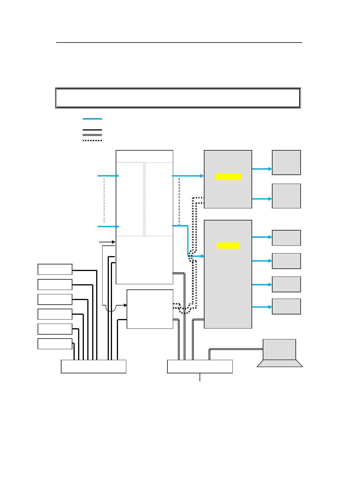
The block diagram below shows an example signal name and tally link system comprised of
a FOR-A video switcher and multiviewer using an MFR-TALM unit. The MFR-TALM is
specifically designed to perform the task of tally data computation, which is ordinarily
undertaken by the MFR main unit, to accelerate the computation. RS-422 ports (1) to (4) are
available for video switcher connection.
Before using an MFR-TALM unit for the system, change Tally Control Unit to MFR-TALM
in the [Main unit Web-based Control: MU Settings page].
VIDEO(SDI)
LAN (MFR-LAN)
LAN (PC LAN)
RS-422
MFR-16SDI
IN1
|
|
|
|
I
|
|
I
|
IN128
MFR-16SDO
OUT1
|
|
|
|
I
|
I
|
|
OUT128
MFR Web Control
MV Layout Editor
Video Switcher
(HVS-2000)