60
4. Settings via MFR-5000 Menus
4-1. Function List
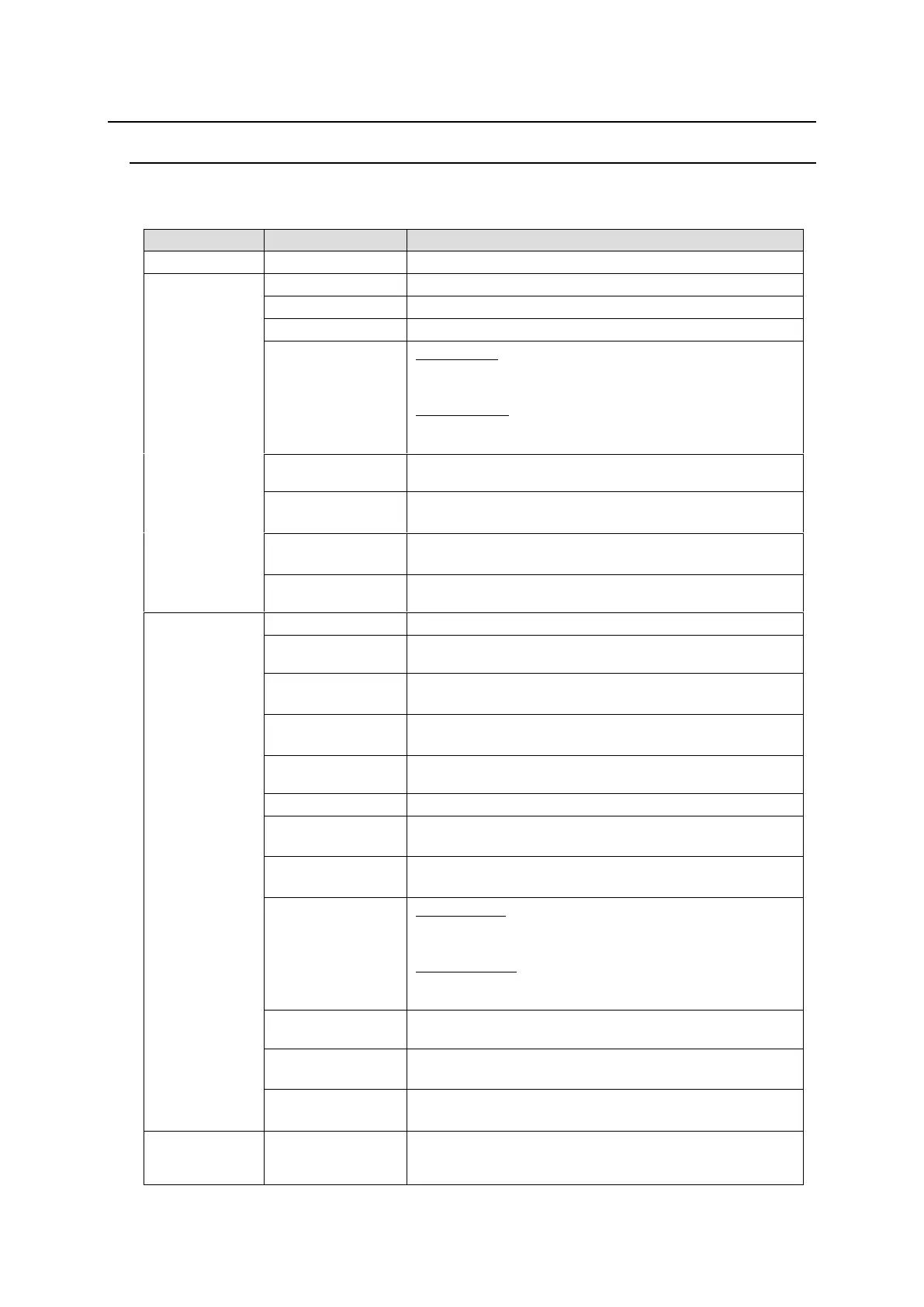
The MFR-5000 front menu display allows you to change or verify settings as shown below.
* The status and alarm display for uninstalled functions will be indicated as “- -“.
Displays the AC alarm. (OK: Normal / NG: Alarm)
Displays the DC alarm. (OK: Normal / NG: Alarm)
Monitors the temperature (OK: Normal / NG: Alarm)
ALARM PS:
Displays the fan alarm for the power supply unit.
(OK: Normal / NG: Alarm)
ALARM FAN:
Displays the fan alarm for the main unit. (NORMAL /
WARNING / ERROR)
Displays the overheat alarm for the power supply unit.
(OK: Running / NG: Stopped)
Displays an alarm for the each card voltage
(OK: Normal / NG: Alarm)
Displays the Secondary CPU condition
(OK: Normal / NG: Alarm)
Displays the CPU and MTX card startup status.
(OK: Startup successful / NG: Startup error)
Displays firmware versions
Displays FPGA versions (CPU cards / MTX cards)
Displays whether the power supply unit is present.
(INSTALLED: Present / NONE: Absent)
Displays whether the CPU card is present.
(INSTALLED: Present / NONE: Absent)
Displays whether an input or output card is present in
each slot. (INSTALLED: Present / NONE: Absent)
Monitors the temperature (°C)
Displays the input voltage of the power supply unit
(OK: Normal / NG: Alarm)
Displays the output voltage of the power supply unit
(OK: Normal / NG: Alarm)
PS STATUS:
Displays the fan alarm for the power supply unit.
(OK: Normal / NG: Alarm)
FAN STATUS:
Displays the fan alarm for the main unit. (NORMAL /
WARNING / ERROR)
Displays the overheating alarm for the power supply
unit. (OK: Running / NG: Stopped)
Displays an alarm for the each card voltage
(OK: Normal / NG: Alarm)
Displays the Secondary CPU condition
(OK: Normal / NG: Alarm)
Allows you to change the Ethernet, menu display
brightness, and reference signal settings, and shut
down slots. See section 4-5. “SETTINGS”