51
3-3. Signal Name and Tally Link System
3-3-1. Standard Configuration
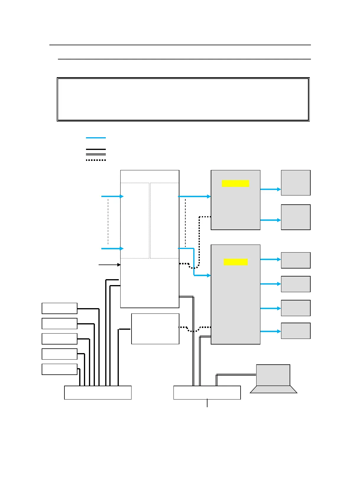
The block diagram below shows a basic signal name and tally link system.
To connect a video switcher via serial connection, use the MFR-5000 SERIAL port or
SERIAL1-4 on MFR-GPI. The signal name and tally link system requires an RS-422
interface. Before connecting devices, set the serial port for use to RS-422 using the
switches on the Card.
► See section 2-1-4. CPU Card Switch Settings or 2-7-4. "Switches on the Card."
VIDEO(SDI)
LAN (MFR-LAN)
LAN (PC LAN)
RS-422
MFR-16SDI
IN1
|
|
|
|
I
|
|
I
|
IN128
MFR-16SDO
OUT1
|
|
|
|
I
|
I
|
|
OUT128
MFR Web Control
MV Layout Editor
Video Switcher
(HVS-2000)