SEP user’s manual Page 36 of 89 Doc no. RD-7243-MA-001-02
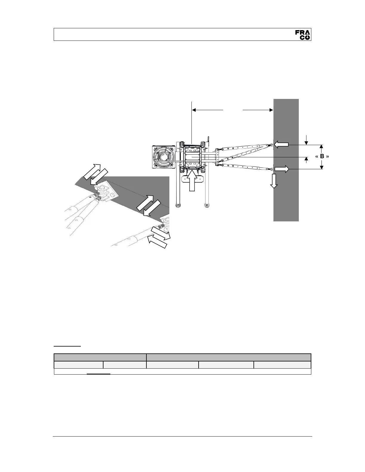
5.4. Anchoring and distribution
The mast anchoring forces are shown in the tables below, depending of the height and
assembly/installation situation. Maximum forces occuring for the represented
assembly/installation geometry are given; they do not yet include safety factors
(UNFACTORED LOADS)
The installation geometry shows anchorage forces according Ax, Ay and By corresponding to
wind forces.
• Typical distance between mast anchors = 30 ft (9 m)
SEE TABLE 2 – GENERAL DATA, ON PAGE 14
• Maximum distance over the last anchor = 0ft (0m)
SEE TABLE 2 – GENERAL DATA, ON PAGE 14
IMPORTANT
Always refer to the engineering quote to get the anchoring loads specific to the structure.
SEP-5000
Load capacitiy = MAX. 5,000 lb (2 270 kg)
Table 11 - Dimensions and anchor forces distribution
Note: The values in the above table apply for every wall tie.