Rev. 5 – Jun 2020 Page 10 of 91
2 SYSTEM SETUP (LINKING)
In a CGM system, modules share audio and power via
10 poles IDC ribbon cables (please refer to the What’s In
The Box section of the manual to see the content of each
module and to have an overview of the available link ca-
bles for various setups, p. 90).
Note that the the Group module does not have a power
socket: it’s because with a CGM configuration you need
to connect only one Group and the Master (if present). With
just two power connections, you will be able to share the
power across your CGM system, with a better ground
handling.
If you accidentally connect more than one group to the PSU,
fear not: it’s not going to damage your system! It’s just use-
less and may not be optimal for ground.
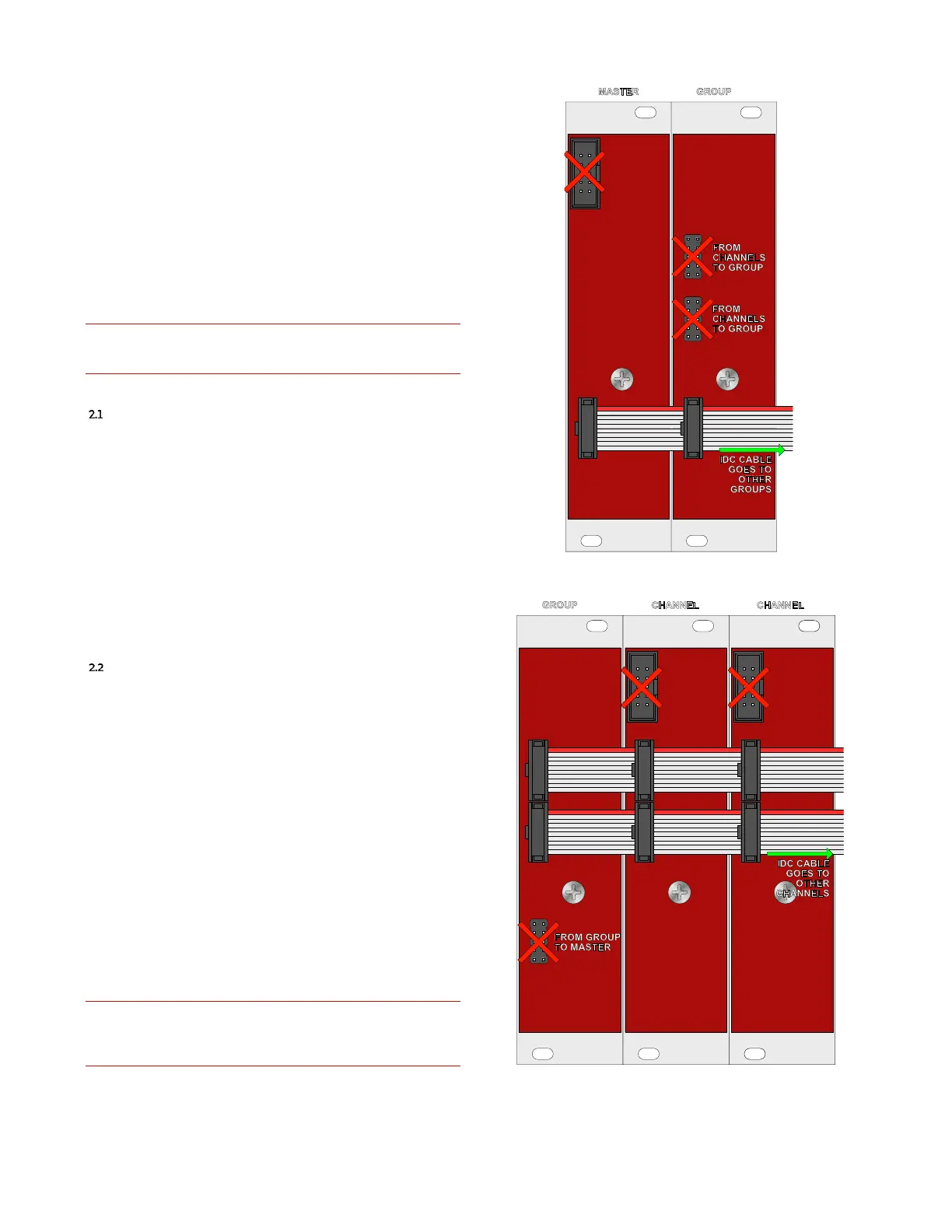
MASTER TO GROUP(S)
Each Master comes with one link cable to connect a
Group to it. You can connect more Groups using a proper
link cable. The Master module, on its back, has two 10 pole
IDC connectors, the one in the top left corner is for pow-
ering, the other in the bottom without any direction is for
linking. Use this one and patch it to the corresponding
one on the Group to establish a connection between them
(in the Group is the one in line –at the same height– of the
one in the Master).
In the example at Figure 10, the cable continues and
goes to other Groups.
GROUP TO CHANNEL(S)
Each Group comes with two link cables to connect one
Group to up to four Channels. You can connect more Chan-
nels (up to eight) using a proper link cable but remember
that at least one Channel is required for the Group to work.
The Channel module, on its back, has three 10 pole IDC
connectors, the one in the top left corner is for powering,
the other two in the center without any direction are for
linking. Use these and patch them together on the differ-
ent Channel you want to link to a Group and on the Group
too (in the Group these are the two connectors in line (at
the same height) with the two on the Channel). It is im-
portant to double check that all the modules are orien-
tated in the same way, and that all the upper connector
are connecter with one IDC cable, while all the lower
connectors are connected with another IDC cable.
In the example at Figure 11, the cable continues and
goes to other Channels.
It is imperative to do not swap connectors! Frap Tools may
not be held responsible in any way for problems or damage
to persons or property or to the device itself if the device is
not connected as indicated above.
Figure 10: Master and Groups connection.
Figure 11: Group and Channels connection.