Rev. 5 – Jun 2020 Page 29 of 91
The top left jack sockets (D.1, D.2) are inputs, the bot-
tom right ones (D.3, D.4) are outputs. The first circuit is
the top one, the second circuit is the bottom one.
The two sections are semi-normalled in order to
achieve 1/2 and 1/4 outputs from a single input. Output
Range switches (D.5, D.6) are useful to obtain unipolar
(0V/+10V) when the switch is high or bipolar signals
(±5V) when the switch is low.
When an audio signal is used as input, it works as a sub-
octave generator (a square or pulse wave is preferred as
carrier). When a clock is used it works as a clock divider.
Bear in mind that if the input is a trig, the output is always
a gate, since
Random clocks from SAPÈL create interesting varia-
ble-length sequences of gates.
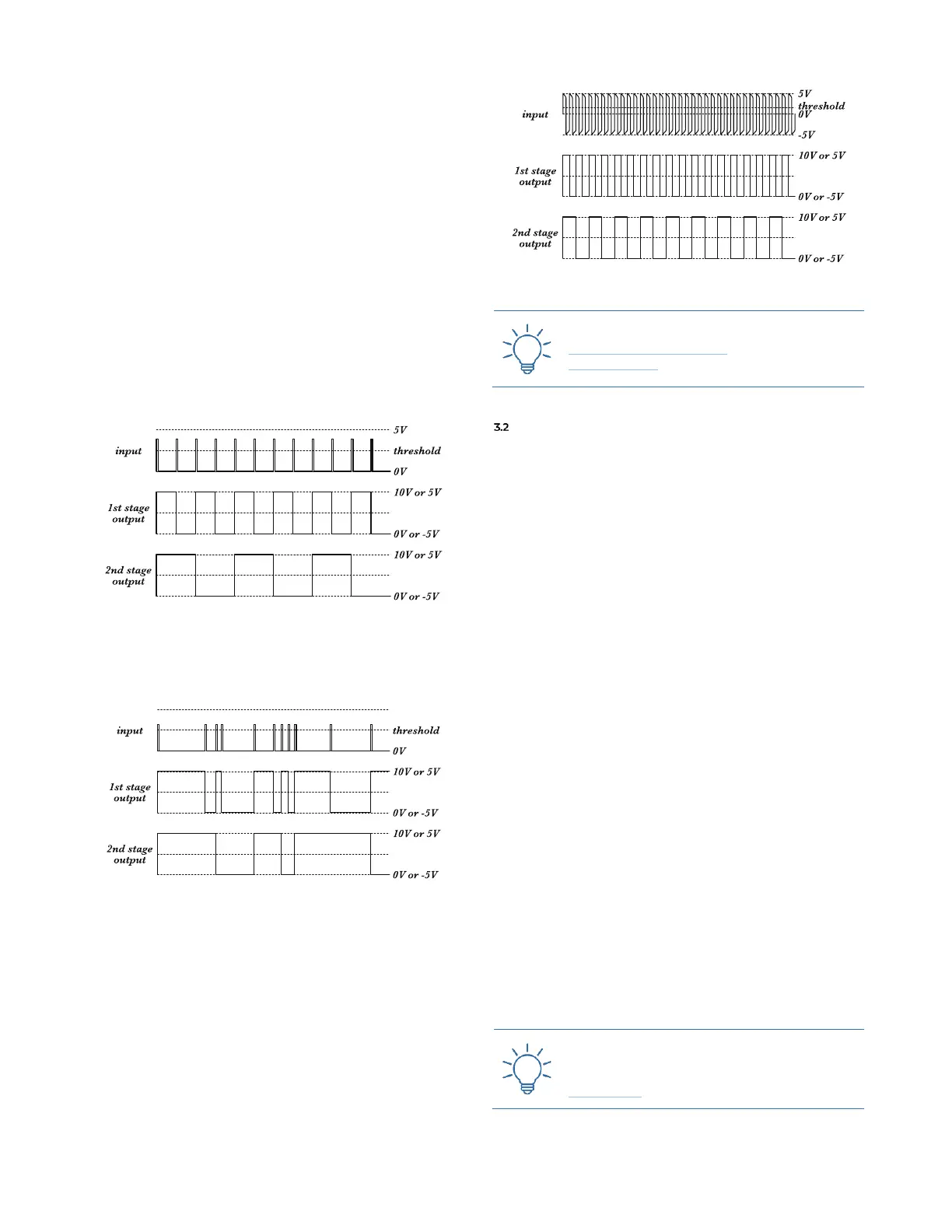
The following example uses a clock as input, obtaining
half and quarter of that clock frequency.
Figure 28: FALISTRI’s DCFD as a double clock divider.
The following example uses a random clock stream as
input.
Figure 29: FALISTRI’s DCFD as a random ip-op.
This last example uses a square-ish wave as audio rate
source, obtaining −1 and −2 octave as output.
Figure 30: FALISTRI’s DCFD as a sub-octave generator.
FOUR-QUADRANT MULTIPLIER
The Four-Quadrant Multiplier (4QM) is a circuit that mul-
tiplies two signals by one each other. It is similar to a
VCA, with the main difference that it welcomes bipolar
signals on both inputs, allowing any possible combination
of positive and negative polarities, which can be thought
of as the four quadrants (hence its name) of a two-dimen-
sional Cartesian plane. It can be thought of as a ring mod-
ulator, a balanced modulator, or a through-zero VCA.
With an exceptional linearity, and a bandwidth from
DC to more than 20KHz, the result of this operation is
completely up to the sources in use.
The two inlets are the jack sockets on the left: the first
from top (B.1) is semi-normalled to the yellow unipolar
output; the second (B.2) is semi-normalled to the green
bipolar one: in this way you can use the yellow as an en-
velope and the green as an audio source, without patch-
ing any cable.
The Level knob (B.3) sets the amount of the two signals,
affecting the Output as a whole (B.4).
The 4 led matrix shows which of the quadrant is cur-
rently in use: the Input 1 (B.1) moves the lights vertically
(negative bottom, positive top), and the Input 2 (B.2)
moves the lights horizontally (negative left, positive right.
3.2.1 Amplitude Modulation & Ring Modulation (2 vs 4
quadrants)
When one of the signals is bipolar and the other is uni-
polar, the 4QM works like an actual linear VCA: this is
the default behavior. This means that if, for example, the
green generator is working as an oscillator, the yellow one
controls its amplitude.