Rev. 5 – Jun 2020 Page 33 of 91
The following chart displays the clock to unit ratios
available: on the left is the number of clocks, on the right,
the number of units.
Clock division
(n clock impulses per 1 unit)
1 clock impulse per 1 unit
Clock multiplication
(1 clock impulse per n units)
Table 3: Clock-to-unit ratio
Each stage length can measure from 0 to 16 units, where
0 means that the stage has no length in the time domain,
therefore it will skip.
The combination of time ratio and units allows ex-
tremely flexible sequences of stages. For example, with
the same clock, it is possible to achieve fast sequences if
the time ratio is set to 1:4 and the stage duration is set to
1 unit, or slow sequences of whole notes if the time ratio
is set to 2:1 and the stage duration is set to 4 units. It is
also possible to have extremely slow sequences by crank-
ing up the stage length to 16 units and the ratio to 24:1…
Another benefit of USTA’s architecture is the efficient
use of stages to create melodies: in the image below, the
melody (a) needs 16 steps and four gates to be performed
on a standard step sequencer with a regular clock (b),
while on USTA it takes only four stages, one per each
musical event (or “note”), each one with its relative dura-
tion and gate (c).
Figure 35: Step versus stage sequencing.
3 BASIC EDITING
AND VISUAL FEEDBACK
The interaction between the musician and USTA hap-
pens both through the navigation menu and more “man-
ual” operations such as button and encoder combina-
tions. Likewise, the visual feedback combines the color-
coded LEDs and the information provided by the default
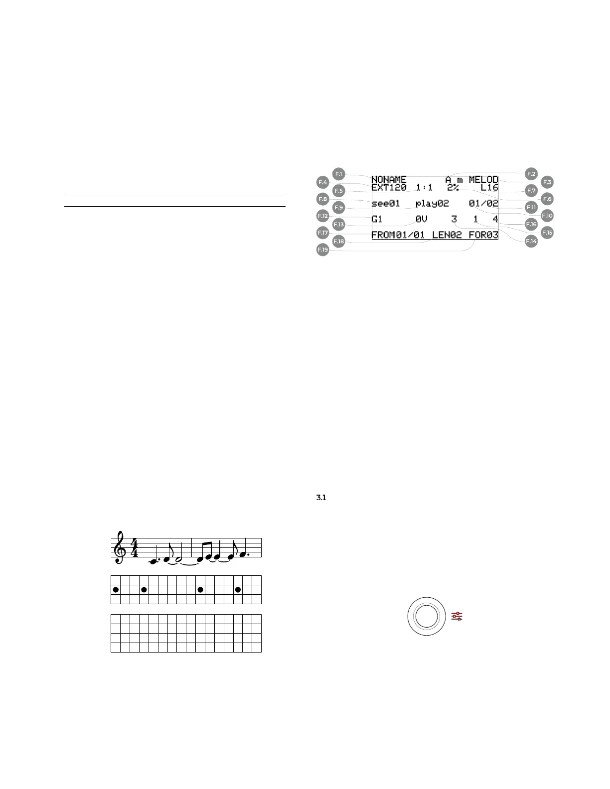
screen on the display (C.5), called Dashboard.
Figure 36: USTA’s Dashboard.
F Dashboard
F.1 Project Name
F.2 Root Note
F.3 Scale
F.4 Clock Source and
BPM/PPM
F.5 Time Ratio
F.6 Swing
F.7 Total pattern length
F.8 Selected pattern
F.9 Playing pattern
F.10 First pattern
F.11 Last pattern
F.12 CV A value
F.13 CV B value
F.14 Length Value
F.15 Gate A value
F.16 Gate B value
F.17 Stage Loop From
F.18 Stage Loop Length
F.19 Stage Loop For
As a rule of thumb, all the data regarding the general
behavior of USTA (track settings) are accessed through
the Project Menu and Track Menu (see below, §§3.1-3.2),
while all the data concerning the very musical content,
such as individual stage data, are set via dedicated encod-
ers and buttons (§3.3 onwards).
EDITING PROJECTS − PROJECT MENU
On its first boot USTA automatically creates an empty
project called NONAME, which is ready to be edited. All the
editing is stored in a volatile memory: to avoid data loss,
it is possible to save the project into an SD card. To per-
form these tasks, push and hold the navigation encoder
(B.14) for three seconds until the Menu LED (C.4) lights
up red: this will open the project menu.
Figure 37: Project Menu LED.
Once there, rotate the same encoder to navigate
through the menu items, and push it to select the desired
one.
CV
GATE
STEP
C C C D D D D D D E E E E F F F
1 2 3 4 5 6 7 8 9 10 11 12 13 14 15 16
GENERIC
SEQUENCER
TARGET
SCORE
USTA
b
a
c
CV
GATE
STAGE
LENGTH
C D E F
1 1 1 1 0 0 0 0 0 0 0 0 0 0 0 0
3 6 4 3 0 0 0 0 0 0 0 0 0 0 0 0
1 2 3 4 5 6 7 8 9 10 11 12 13 14 15 16