Rev. 5 – Jun 2020 Page 7 of 91
The former is a discrete signal with two levels only (“off”
and “on”, “low” and “high”). In our modules it is associ-
ated with square shapes: the reason is that squares have
only two kind of lines (vertical and horizontal), in the
same way a gate or rig signal has only two possible states,
on and off.
Figure 3: Square shapes.
The latter is a continuous signal (or ‘analog’ in its clos-
est meaning). Is associated with round shapes because cir-
cles can be thought of as having infinite sides, in the same
way an analog signal has infinite values.
Figure 4: Round shapes.
A subgroup of audio analog section is the stereo audio.
As you can notice in the CGM series, the group and mas-
ter modules feature stereo in and out out: here, the
left/mono is connected to the solid-colored area, while
the right is connected to the ring that surrounds it. The
reason is that the left output is always the primary (be-
cause it can be used as a mono output as well), while the
right one is more of an accessory to it.
Figure 5: Stereo audio.
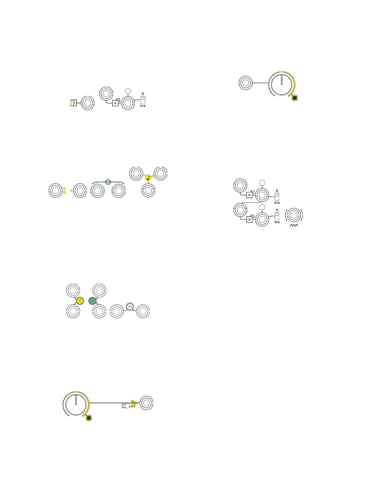
3 LINES (SOLID, DOTTED, DASHED)
A solid line relates two or more elements of the circuit.
It stands for manual control, which means that a given
knob or switch directly affects the signal passing through
the circuit from an input or to an output.
Figure 6: Solid lines.
A dotted line stands for external CV control, and it of-
ten relates a jack socket to a manual control such as a
knob or a slider. It means that the specific parameter can
be voltage controlled.
Figure 7: Dotted lines.
A dashed line relates two or more inputs or two more
outputs: it means that they are semi-normalled, or, in
other terms, that the signal going to one input or coming
from one output is mirrored by the other jack sockets con-
nected by a dashed line. Such behavior is automatically
overridden once a cable is plugged to another jack socket
(thus “breaking” the normalization).
Figure 8: Dashed lines.
4 COLOR CODING
As a rule of thumb, if a module performs more than one
function, the respective controls are marked with differ-
ent colors. In other words, a given color relates to one and
only one section of the module design. In case a module
features two “mirrored” sections (such as SAPÈL’s or
FALISTRI’s generators, or CGM Group’s FX sends),
they are marked in yellow and green.
5 COMBINATIONS
All the elements can be combined. For example, an ar-
row within a square pointing towards a jack socket means
that it is a gate/trig input; if a dotted line connects a jack
socket to a knob, and a solid line connects the same knob
to another jack socket, it means that the signal outputted
from the second jack socket can be modified either man-
ually via the knob or automatically via an external CV
patched to the first socket.