Rev. 5 – Jun 2020 Page 37 of 91
third layers (respectively marked by green and blue
LEDs) manage possible variations of the red layer’s value.
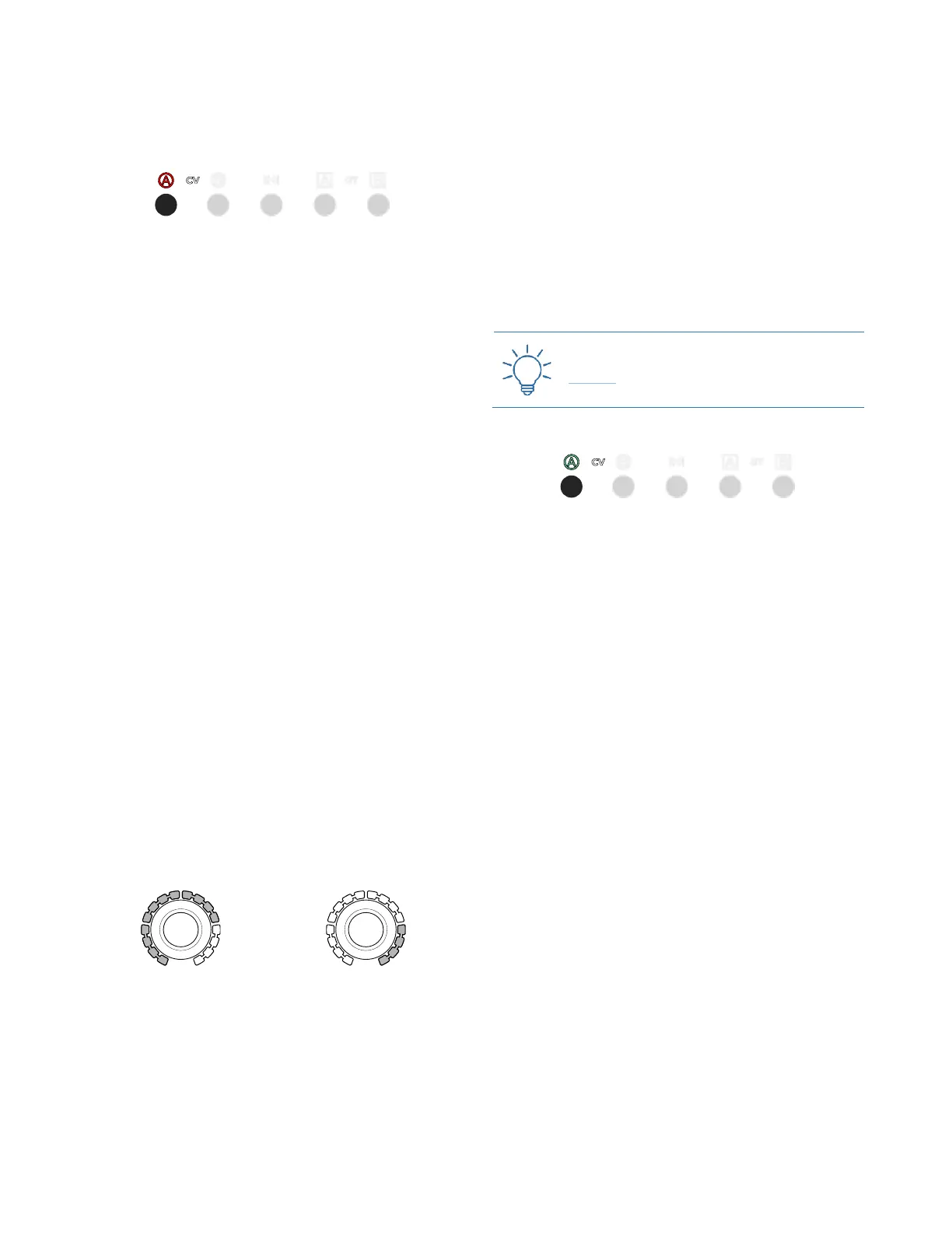
3.4.3.1 Red CV Layer: Value
Figure 40: CV A’s Value layer is selected.
The red layer is displayed by default once a channel is
selected. It contains the data concerning the stage value
(i.e. the actual voltage that will be output by USTA).
Such values can be quantized (as in 12 semitones) or
raw (i.e., continuous voltages with down to 1mV of reso-
lution). The default setting is Pitch for CV A, which can be
used for generating melodic lines, and Raw for CV B,
which can thus be used to add dynamics and to modulate
other “musical” parameters such as filters, VCAs, tim-
bre… It is possible to change these settings and have both
CVs in raw or quantized mode (see below §8.1).
In order to edit this value, select the desired channel (CV
A or CV B) through its button (B.6, B.7), then rotate the
encoder corresponding to the step you want to edit (A.1).
Each time you edit a stage value, the fourth row from the
top of the dashboard updates showing the CV A, CV B,
Length, Gate A, and Gate B for that stage on that pattern of
that track: this is helpful to understand relationships of
the same stage across channels.
Pitch CV channels display notes using the standard no-
tation letters from A to G followed by the octave number,
while Raw CV channels display Volts. The octave num-
ber can be set to change on A or C through the reference
note (see below §9.4).
In Pitch mode, the Stage Arc (A.2) will also precisely dis-
play the selected note. 12 LEDs from left to right display
the note value in half steps: none for C, one for C♯/D♭
and so on until eleven lit LEDs stand for B. The note ref-
erences apply when the project reference note is C. To
change it to A (see below §9.4). The four remaining LEDs
will display the octave, from right to left. For a precise
chart of this visualization system see LED Pitch Tables,
§9.6.
Figure 41: The grey LEDs display
the semitones.
Figure 42: The grey LEDs display
the octaves.
By default, USTA works with the 12-semitone equal
temperament, which divides the octave into 12 equally
spaced intervals. It is possible, however, to change this
setting and work with other more complex octave
divisions such as 15, 19, 22 or 24 intervals, on which see
below §9.2.
For raw channels, such as channel CV B by default, the
encoder increases the stage CV value by steps of 0.05V
or 50mV when turned clockwise. In this mode, coarse
and fine edit is possible: with the Coarse button held
down, the encoder steps are of 0.5V (500mV), while with
the fine (Esc held down and Coarse held down) steps are
of 0.001V (1mV). Visual feedback of the value is dis-
played on the 16 yellow LED of each Stage Arc, scaling
the 10V of range to 0/16 LED: in other words, each LED
shows 0.625V.
Practice the Raw voltages with this Technique:
Raw CV
3.4.3.2 Green CV Layer: Variation Index
Figure 43: CV A’s Variation Index layer is selected.
The green layer is accessed by pressing the channel but-
ton (B.6 or B.7) a second time: it controls the probability
that USTA will shift the red value up or down in a given
bipolar range (see below, Blue CV Layer).
By default, the stage values are at 0, with the Stage Arc
(A.2) completely off: this means that there is no chance
that the note (or voltage) will change, so USTA will stick
to the value assigned in the red layer.
By turning the Stage Encoders (A.1) clockwise, you in-
crease the chance that the note will be replaced with an-
other one (Variation Index), picked by a pool of values
whose range is defined by the blue layer (Variation Range,
see the following chapter). In this mode, USTA tosses a
coin at every stage with an Index bigger than 0 and decides
whether the stage will pick the Value defined in the red
layer or shift it.
When 8 LEDs out of 16 of the Stage Arc are lit up, the
chances are 50-50: the probability that the defined value
will be played or not are the same. When all the 16 LEDs
are lit, it is certain that another note or voltage will be
evaluated.
It does not mean, however, that the Value defined in the
red layer will not play at all, since it is still within the Var-
iation Range defined by the blue layer, so it is possible that
it might be picked by the coin toss.