Rev. 5 – Jun 2020 Page 17 of 91
Given that n can be any number from 1 to 6, there are 6
possible ranges of values that this circuit can generate:
Number of generated voltages
Table 1: n values for 2
n
quantized random voltages.
Please note that higher is the number, the larger be-
comes the range of voltages (or “notes”) that are gener-
ated, starting from 1 (0V) up to 64 (5.25V). This will guar-
antee the musician more control over the final output and
will lead to more expressive results: for example, a low n
value will always generate smaller intervals and low
pitches, while a high hone may provide larger leaps from
one semitone to the other, as well as higher notes. Please
refer to the graph below (Figure 15) for a graphic repre-
sentation of the exponential note distribution across all
the n settings:
Figure 15: 2
n
quantization chart.
The n+1 output (B.2) is quantized in 1V steps, or octaves
in the 1V/oct scale. In this case, the Value knob (B.3) sets
the number which will be summed to 1, which, in turn,
determines the number of different octaves that may be
generated by the circuit. Again, given that n can be any
number from 1 to 6, there are 6 possible ranges of octaves
that this circuit can generate:
Number of voltages generated
Table 2: n values for n+1 quantized random voltages.
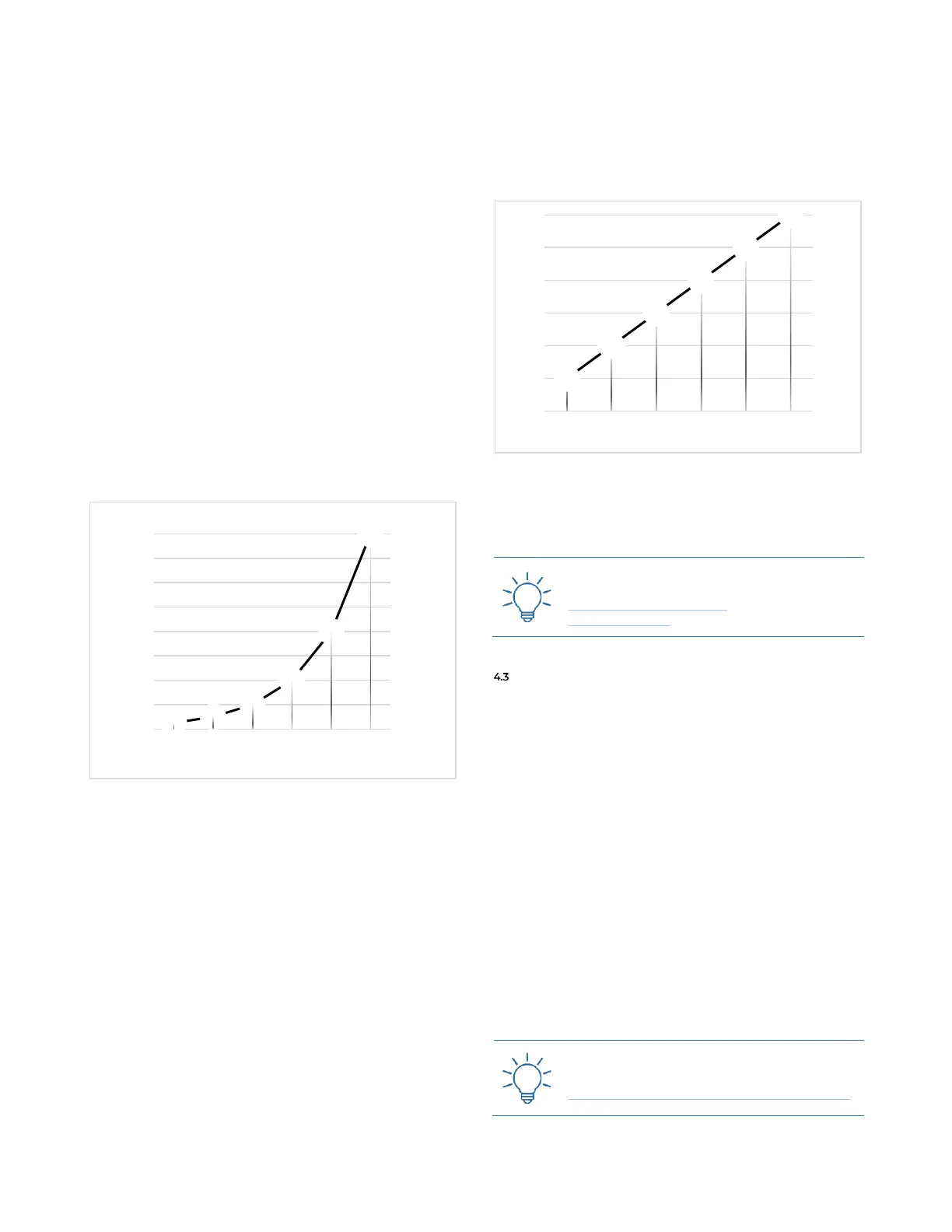
Even in this case, that higher is the number, the larger
becomes the range of voltages (or “octaves”) that are gen-
erated, starting from 1 (0V) up to 7 (6V). Please refer to
the graph below (Figure 16) which displays the linear in-
crement of the octaves across the different n settings.
Figure 16: n+1 quantization chart.
Both the 2n and the n+1 can be controlled via external
CV (B.4, B.7) thus allowing the musician to automatically
vary the range of values to be outputted.
Practice the use of the n+1 output with these
Techniques:
Ratcheting-Like Effect #2
Voice Spread #1
FLUCTUATING RANDOM OUTPUT AND GLOBAL RATE
OF CHANGE (RANDOM CLOCK DENSITY CONTROL)
The main purpose of this section is to output (C.1) a
continuous, fluctuating random voltage which ranges 0
to 7.5V and whose rate of change (or “frequency”) is con-
trolled by its potentiometer (C.2).
This random generator is the only one (in both the S&H
clusters) which is not affected by the main clocks or gates;
however, on the other hand, it can affect the clock gener-
ation itself.
The second purpose of this section, is in fact, to control
the rate of change of the random clocks: by rotating the C.2
knob clockwise, both the fluctuating voltage frequency
and the random clock density (let it be in more than or less
than mode) are increased, and vice versa.
Just like for the quantized voltage generators, this pa-
rameter can be modulated with any CV using the its CV
input (C.3). The external modulation will affect both the
fluctuation rate and the random clock density.
Practice the Global Rate of Change with this
Technique:
Fluctuating Random & Global Rate of Change
2
4
8
16
32
64
-0,75
0,25
1,25
2,25
3,25
4,25
5,25
0
8
16
24
32
40
48
56
64
1 2 3 4 5 6
Volts
Number of stages
n value
2
3
4
5
6
7
0
1
2
3
4
5
6
1
2
3
4
5
6
7
1 2 3 4 5 6
Volts
Number of stages
n value