Rev. 5 – Jun 2020 Page 21 of 91
3 AUDIO OUTPUTS
FUMANA’s main audio outputs are the three in the top
left area: All (B.1) outputs all the bands, while Odd (B.2)
and Even (B.4) output respectively only the odd and only
the even bands.
In addition to these, 16 direct outputs are also provided
(B.6), which are located on the top of each band. The
main difference between these and the other three out-
puts is that, while the All, Odd and Even, are sums of
groups of bands after their respective VCAs, these 16 band
outputs are pre-VCAs outputs, directly from the bandpass
filters.
These are very useful in case it is needed to process in
parallel only a single band or a group of selected bands.
In that case the 333 module can be very helpful, since it
is capable of summing perfectly up to 7 signals into a sin-
gle jack.
The use of the individual filter outputs does not affect
their respective band’s presence in the Odd/Even/All out-
puts: these stages are completely independent.
The Odd and Even outputs also feature a phase inversion
switch (B.5): this switch may be useful in case you want to
merge one of that signal with the All output, and dynam-
ically emphasize (phase summing) or dynamically atten-
uate (inverted phase summing) for example only the Even
bands (or Odd, depending on needs).
The result of the sum of Odd and Even outputs is slightly
different from the All output. This is because the All out-
put uses an additional low pass filter at 18KHz in order
to obtain a less “edgy” upper end, often resulting when
using dense signals and/or heavy modulations (you can
have a clear view of this looking at the Transfer Function
Details). In case you need a crispier sound, consider using
the Odd+Even combination.
4 AUDIO PROCESSING
AND MODULATION PATH
FUMANA’s filterbank processes the sound patched to
the Main input by varying each band’s amplitude through
a VCA circuit. Such variation can be achieved in four
different ways, many of which can easily co-exist:
· through the individual band faders;
· through the individual band CV inputs, right below
the faders;
· through the Macro Spectral Editing tools (Tilt and Scan)
· through the spectral transferring function performed
by any sound patched to the Mod input.
The result of all these modulations is outputted by the
All, Odd and Even outputs, and it is visually displayed by
the 16 blue LEDs placed on the 16 band faders, whose
intensity graphically displays the amplitude of the respec-
tive band after any modulation applied. The relationship
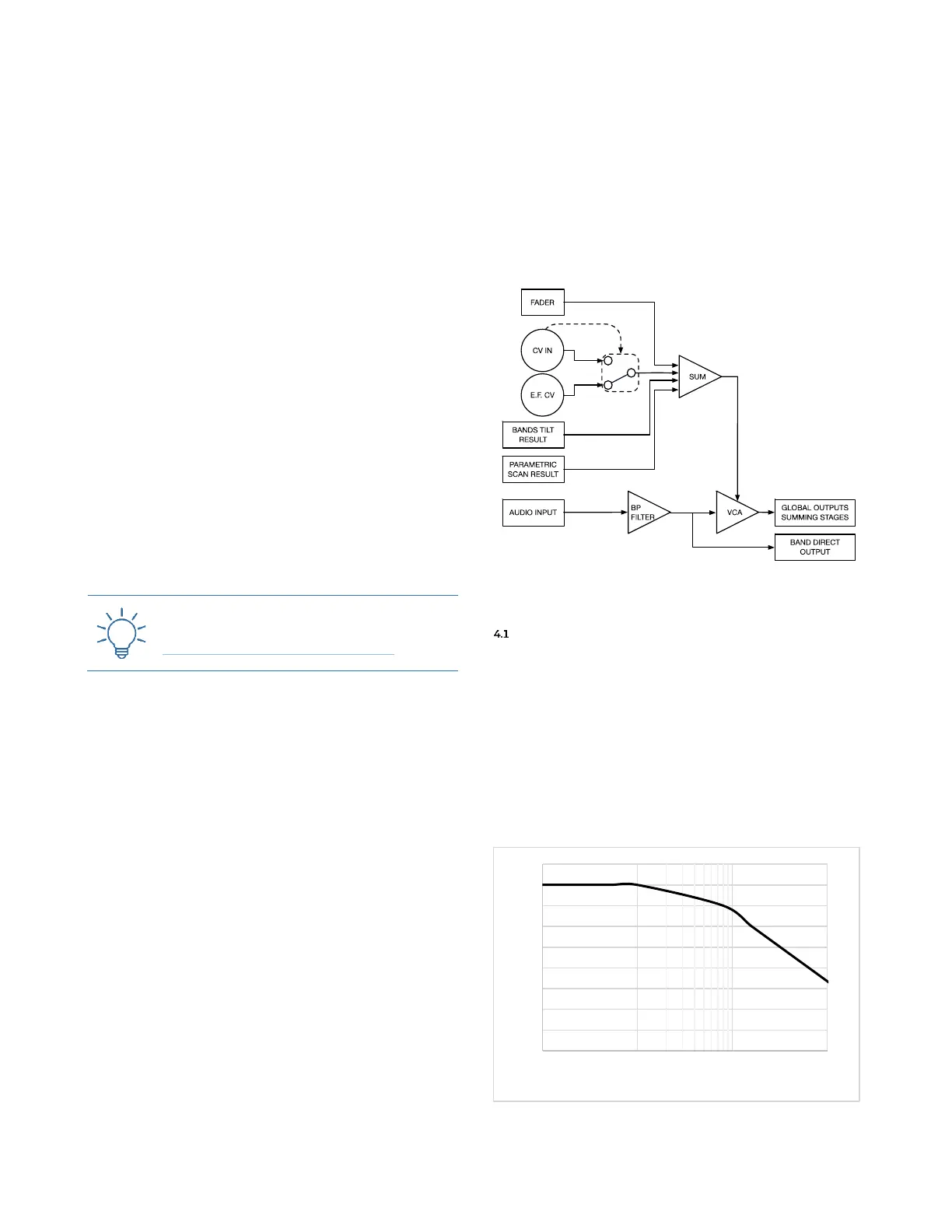
of the modulations is displayed in Figure 18, and it will
be further explained in the next paragraphs.
Figure 18: FUMANA’s modulation routing.
FADERS AND CV
The main CV comes from the 16 faders (C.1), one per
band, on the main panel. In the lowest position the VCA
is closed: raise the fader to increase the selected band’s
amplitude. This operation can be automated through the
16 individual jack sockets below each fader (C.2), which
provide inputs for external CVs. The CV inputs welcome
any signal either bipolar or unipolar, even at audio rate,
up to ~1000Hz (after which a lowpass filter is applied, see
Figure 19): it is thus possible to perform AM over an in-
dividual band!
Figure 19: CV frequency roll-off.