Rev. 5 – Jun 2020 Page 38 of 91
3.4.3.3 Blue CV Layer: Variation Range
Figure 44: CV A’s Variation Range layer is selected.
The blue layer is accessed by pressing the channel but-
ton (B.6 or B.7) a third time: it determines the range of
values which the variation index will refer to (the Variation
Range, i.e., the values that may or may not be “picked”
by USTA instead of the one defined in the red layer).
The blue layer lets you choose the bipolar range of val-
ues that could be selected by USTA after tossing the coin.
Such values are expressed in semitones for the Pitch chan-
nels and millivolts for the Raw ones. The range incre-
ments by steps of ±2 semitones each for the quantized
channels (up to ±32 semitones) and in steps of ±314 mV
each for the raw channels (up to ±5.024 V).
While some extreme settings of the green and blue layer
might translate into a behavior comparable to the one of
a random voltage generator such as SAPÈL, their overall
approach is completely different, if not the opposite.
SAPÈL is a true random module whose voltages are sam-
pled using analog noise as a source, therefore there is no
chance that a sequence of values will repeat itself over
time. USTA, on the other hand, uses a digital “coin toss”
algorithm to randomly pick a value within a given range
defined by the user, whose result totally depends on the
Value chosen as default. In other words, while SAPÈL
shapes its stream of random voltages by “subtraction”, i.e.
through sample-and-hold, quantization, probability dis-
tribution, USTA progressively “expands” the range of
values according to the musician’s instructions.
3.4.4 CV Stage Colors
Each stage can be played in three different ways called
Stage Colors, which can be accessed by pushing the Stage
Encoder (A.1) multiple times. In order to better understand
the relationship between Stage Colors and the Layers de-
scribed in the previous chapters, one could say that Layers
affect the content, i.e. the values that the stage will play,
while Colors affects the form, i.e. the way in which such
values will be played.
Table 6: CV Colors comparison.
The first CV Stage Color, called Flat, is selected by default
once a channel (CV A or CV B) is selected, and it is indi-
cated by a blue Stage LED (A.3). It simply plays the stage
value (whether selected or randomly shifted) for the
whole stage duration. It is the normal behavior you would
expect from a traditional sequencer.
The second CV Stage Color, called Slide, is accessed by
pushing the Stage Encoder (A.1) once, and it is indicated by
a green Stage LED. In this mode, instead of playing the
defined stage value, USTA will automatically generate a
linear ramp from the previous value to the new one, in a
sort of “glide” effect, interpolated for the whole length of
the stage.
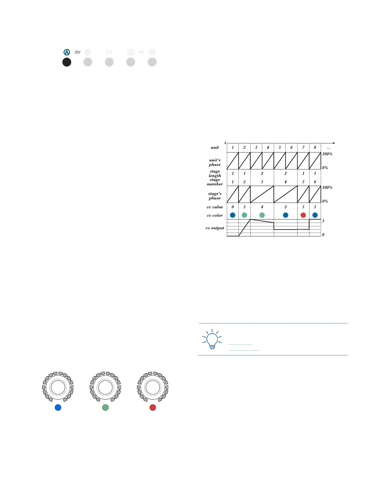
Figure 45: Unit phase, Stage phase, and CV output.
The third CV stage color, called Skip, is accessed by
pushing the Stage Encoder a second time, and it is indicated
by a red stage LED. In this mode the stage skips the volt-
age generation, retaining its length (see below): USTA
will simply play the last value generated by the previous
stage.
Push the Stage Encoder again to return to the blue color
layer.
3.4.4.1 USTA Slide vs FALISTRI Slew
The slide color may be similar to a slew limiter circuit
(see FALISTRI §3.2.3), but it is very different in design
and concept. A slew limiter integrates two values and
generates an ascending or descending ramp with a fixed
duration (lag). Such lag time is arbitrarily set and often
allows the target CV to be noticeably performed by the
machine. USTA’s slide, on the other hand, automatically
calculates the lag time, which corresponds to the whole
stage duration. This means that the stage value set in the
blue layer is technically never played, becoming the