Rev. 5 – Jun 2020 Page 6 of 91
BEFORE STARTING
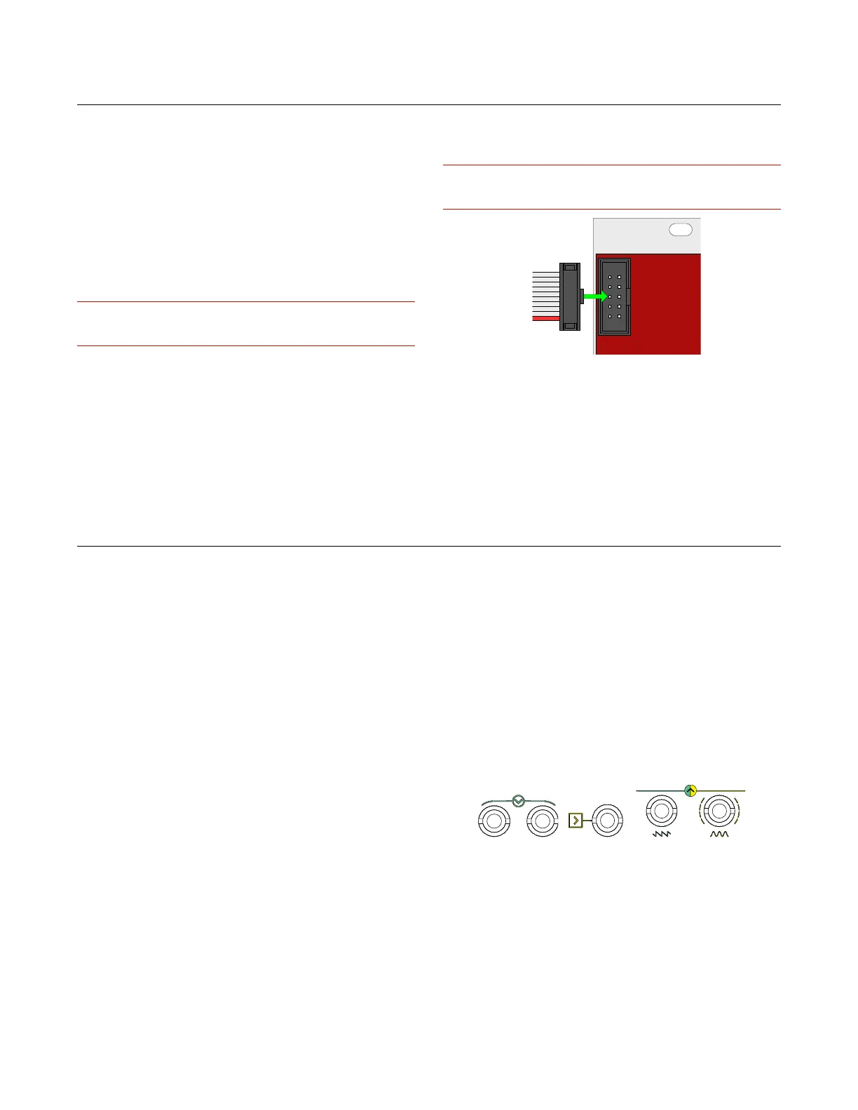
1 CONNECTING THE POWER
To connect the power cable, carefully follow these two
rules:
· the power connector on the module is the keyed one
in the top;
· the red line on the cable should be placed matching
the −12V side on your power board: please double check
with your power boar supplier that the marked side is the
−12V.
Frap Tools may not be held responsible in any way for prob-
lems or damage to persons or property or to the device itself,
if the device is not connected as indicated above.
2 MOUNTING THE MODULE
After connecting the power as explained in the previous
section, install the module in your case using all the 2 or
4 screws provided. Make sure that the module is safely
and tightly connected to your Eurorack case.
Frap Tools modules use the standard Eurorack orienta-
tion and color-coding: the red line on the power cables is
placed at the bottom and stands for the −12V. Please
double check with the power system you want to use that
it adopts the same powering system.
Frap Tools may not be held responsible in any way for prob-
lems or damage to persons or property or to the device itself,
if the device is not connected as indicated above.
Figure 1: Power connection.
3 WARM-UP AND WORKING TEMPERA-
TURE
For best performances, we suggest letting the Frap
Tools modules warm up at least around 20 minutes prior
to use it [tested at 25°C]. It is absolutely normal that they
feel warm when touched.
INTERFACES
Here at Frap Tools, we put a lot of effort into designing
a proper user interface for each of our modules.
By “proper user interface” we mean essentially three
things:
1. it must convey the module’s identity at a glance;
2. it must allow for a smooth creative workflow;
3. it must be pleasant to look at.
Moreover, we want our interfaces to be clear, but not
self-explanatory (or, in other terms, cryptic, but not cha-
otic).
The reason for doing so is that, in our vision, the musi-
cian should master the “code” of the instrument before
playing it: a piano does not have the note names on its
keys, a violin does not have marks on its neck — it is up
to the musician to practice and learn how the instrument
works.
In the same way, our modules do not have labels such
as ‘frequency’ or ‘decay time’: instead, they are replaced
with a system of symbols and colors that try to be as con-
sistent as possible. Moreover, a musician approaching
our modules through a “conventional” labeling system
might be tempted to assume that the module behaves in
an ordinary way, which sometimes is not completely cor-
rect.
The modules are explained in detail further in this man-
ual. However, to allow the musician to get acquainted
with the overall symbol system, we provide here a brief
guide to “decode” the most recurrent elements of the
“Frap environment”.
1 ARROWS (INPUT, OUTPUT)
An arrow can mean either an input or an output, ac-
cording to its position: if it points towards one or more
jack sockets, it is an input; if it points away from one or
more jack sockets, it is an output.
Figure 2: Arrows.
2 SQUARE AND ROUND SHAPES
All the modular world revolves around voltage. The
most basic distinction is, conventionally, between voltage
used for timing pulses (trigs or gates) and voltage used for
audio signals or CV.