Rev. 5 – Jun 2020 Page 11 of 91
GROUP JUMPERS CONFIGURATIONS
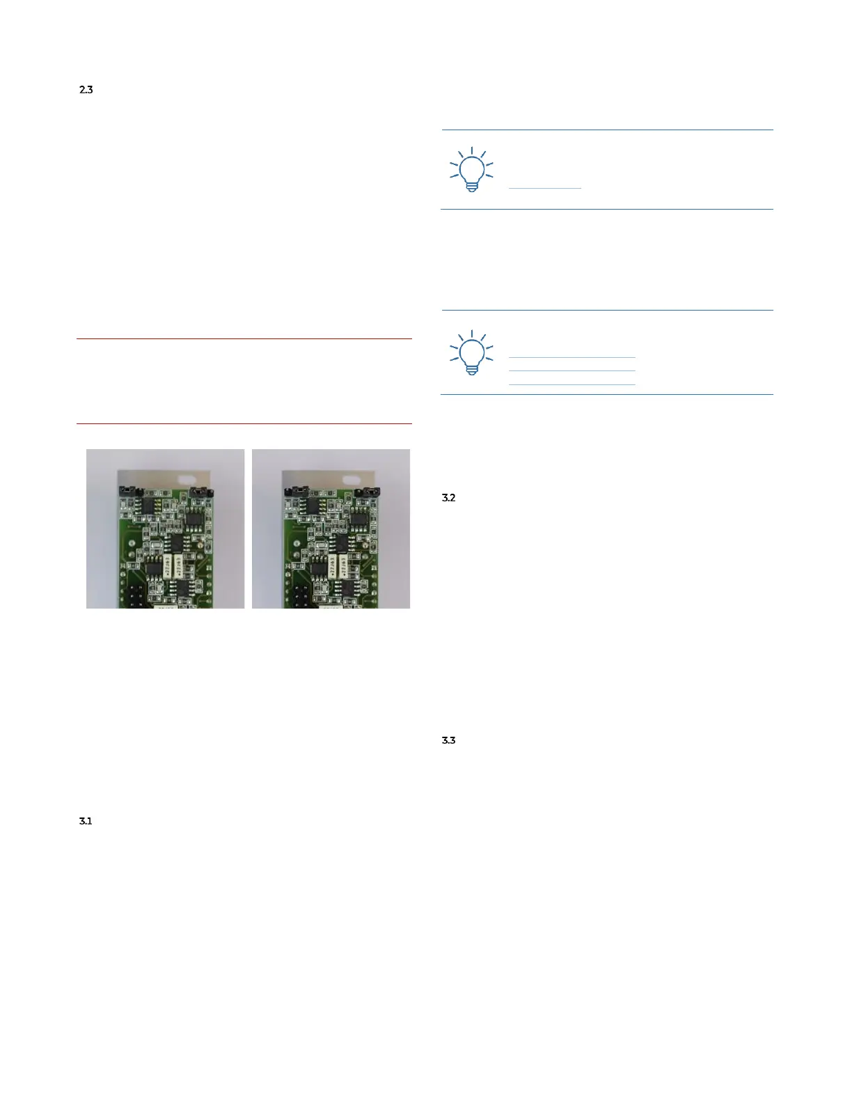
Group L/R output can be configured in two ways: look-
ing at the PCB from the back, if the two jumpers on the
top of the module are connected to the pins 2-3 (from the
left) the group outputs the sum of the signals from all the
channels connected to the group itself, and the signals
coming in from the yellow and green return. Otherwise,
if the two jumpers on the top of the module are connected
to the pins 1-2 (from the left) the group outputs the sum
of the signals coming in from the yellow and green return
only.
Please note that these jumper configurations will not af-
fect the signal sent from the Group to the Master via the
IDC cable: only the group outputs on the front panel may
be configured.
It is imperative to do not connect the jumpers to any other
connector except the two mentioned in this section and
shown in the pictures below. Frap Tools may not be held re-
sponsible in any way for problems or damage to persons or
property or to the device itself, if the device is not connected
as indicated above.
In Figure 12, the Group outputs the sum of the signals
coming in from the yellow and green return only.
In Figure 13, the Group outputs the sum of the signals
from all the channels connected to the group itself, and
the signals coming in from the yellow and green return.
3 CHANNEL
MAIN VCA & DIRECT OUT
The top left input of each channel is its mono input
(A.1). The connected signal goes directly to the main
VCA (red): it is the second row of parameter, with a jack
socket on the right and a pot on the left. This stage can
also be identified as gain stage. The CV input range ac-
cepts both modulation signals from 0÷5V or 0÷10V.
When a CV is patched to the VCA Level CV Input (A.4), the
Level pot (A.3) attenuates the CV; when nothing is
patched to the jack socket, the pot works as the unique
primary control for the VCA Level (or for the gain stage).
This section also features a post VCA peak LED.
Practice the VCA Level CV Input with this
Technique:
Sidechain #1
The jack socket on the top right is the Direct Output (A.2).
It is not a duplication of the input, but a post VCA direct
output: it is extremely useful in case of multitrack record-
ing or parallel processing of signals.
Practice the use of the Direct Output with
these Techniques:
FUMANA Feedback #1
FUMANA Feedback #2
FUMANA Feedback #3
The last control is the Pre/Post Switch (A.5), which lets
you define how the direct output works: pre-fader (up, red
dot), or post fader (lower, white dot).
SENDS
The two Sends (yellow and green) work in the same way
and receive the signal after the main red VCA. The Send
Level CV input (B.2) range accepts both modulation sig-
nals from 0÷5V or 0÷10V. When a CV is patched to the
Send Level CV input, the Send Level pot (B.1) attenuates that
CV, while when nothing is patched to the jack socket,
then the pot works as the unique primary control for the
VCA (that is, the signal sent to the send bus). The last
control is the Send Pre/Post switch (B.3) which lets you de-
fine how the send works: pre-fader (up, yellow/green
dot), or post fader (lower, white dot).
PAN, FADER AND OTHER CONTROLS
The Pan control lets you distribute the processed signal
across the stereo image. The pot (A.6) work as in any
other mixer and the CV jack socket connected to it (A.7)
accepts both positive and negative signals (range
−5V÷5V).
The more the positive CV increases, the more the signal
is distributed to right, and vice versa for negative CVs and
the left channel. In case of modulation with a bipolar CV,
the potentiometer works as an offset.
The Channel Fader (A.8) sets the channel final volume as
in any mixers. It can also be the reference when you are
using post-fader settings in the sends or in the direct out-
put.
Below that control there are three performance-ori-
ented buttons with their relative LED: from left to right