
A
Anthony SchultzSep 9, 2025
What to do if the wheels are contaminated on my Fronius Welding System?
- JJohn McdonaldSep 9, 2025
If the Fronius Welding System's wheels are contaminated, clean the wheels.
What to do if the wheels are contaminated on my Fronius Welding System?
If the Fronius Welding System's wheels are contaminated, clean the wheels.
Why is the oscillation not working on my Fronius Welding System?
If oscillation does not work on your Fronius Welding System, it could be due to: * The oscillation form is set to 'without oscillation': Adjust the Oscillation Mode to trapezoidal, triangular, or rectangular. * Oscillation parameters are incorrectly set: Adjust the oscillation parameters.
How to fix 'Low Bat. Error 1' on Fronius Welding System?
If you get a 'Low Bat. Error 1' on your Fronius Welding System, it means the rechargeable battery pack is nearly flat. Charge up the rechargeable battery pack with the charger.
Why doesn't the power source start on my Fronius Welding System?
If the Fronius Welding System power source doesn't start, it could be due to the 'Welding I/0/TEST' toggle switch being in the '0' position. Turn the toggle switch to the 'I' position. Alternatively, the connecting cable between the carriage and power source might be damaged; in that case, check the connecting cable and replace it if necessary.
What to do if the display does not light up on my Fronius Welding System?
If the display of your Fronius Welding System does not light up, there could be several reasons: * The rechargeable battery pack may be discharged: Charge the rechargeable battery pack with the charger. * There may be no power to the electronic module: Check the connections between the compartment and the electronic module. * The electronic module may be damaged: Replace the electronic module.
Why is the magnet overheated in my Fronius Welding System?
If the Fronius Welding System's magnet is overheated, it's likely because the working temperature exceeds 150 °C. To resolve this, adjust the welding conditions to reduce the working temperature.
What does 'Error 7' mean on my Fronius Welding System?
If you see 'Error 7' on your Fronius Welding System, it indicates an oscillation unit motor controller internal error. Contact Fronius service technicians.
What does 'Error 6' mean on my Fronius Welding System?
If you see 'Error 6' on your Fronius Welding System, contact Fronius service technicians.
What does 'Error 5' mean on my Fronius Welding System?
If you see 'Error 5' on your Fronius Welding System, it indicates a carriage motor controller internal error. Contact Fronius service technicians.
What does 'Error 4' mean on my Fronius Welding System?
If you see 'Error 4' on your Fronius Welding System, it indicates a save/load error, possibly due to damage to the mobile controller memory. Contact Fronius service technicians.
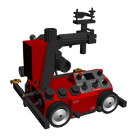
Introduction to the ArcRover 22 welding carriage and its function.
Explains the function and use of the operating instructions.
Explains safety symbols and their meanings: Danger, Warning, Caution, Note, Important.
Details copyright information and requirements for qualified personnel.
Describes the ArcRover 22 as a portable, battery-powered welding carriage and its design features.
Lists situations where the ArcRover 22 is used for longitudinal weld seams.
Defines the correct usage and intended applications for the ArcRover 22 carriage.
Outlines improper uses and restrictions on modifications to the carriage.
Emphasizes the importance of keeping instructions handy and the operator's duty to instruct users.
Details potential hazards from the battery pack, including leaks, overheating, and vapors, with recommended safety measures.
Provides instructions for the proper disposal and recycling of rechargeable batteries and devices.
Guidelines for using the charger and rechargeable battery pack, including charging procedures and handling.
Specifies ambient temperature, humidity, and air quality requirements for operation and storage.
Describes the rating plate and safety symbols on the carriage which must not be removed.
Warns about hot surfaces on the carriage during operation and recommends protective measures.
Lists and illustrates all items included in the ArcRover 22 carriage package.
Illustrates and labels the components of the ArcRover 22 carriage when equipped with an oscillation unit.
Illustrates and labels the components of the ArcRover 22 carriage when not equipped with an oscillation unit.
Lists and describes various accessories for the ArcRover 22, such as drive wheels and battery packs.
Details different types of lateral guides available as accessories for the carriage.
Describes the accessory for mounting a second welding torch.
Lists and describes optional components like oscillation units and motor slides.
Identifies and explains the function of various controls and connection points on the carriage.
Further details carriage components including the battery compartment and control unit switch.
Explains the display, adjusting dials, and toggle switches on the carriage control panel.
Describes the information displayed in the main menu, including program status, battery level, and errors.
Identifies the components of the charger and rechargeable battery pack set and their functions.
Explains how to navigate menus, turn adjusting dials, and enter parameter values.
Details parameters within the CAR menu, including Travel Speed, Total Path, Segment Width, and Gap.
Covers remaining CAR menu parameters like Back Filling, End Crater Filling, and Direction/Stop.
Introduces OSC menu parameters for oscillation control, including Speed and Path.
Details OSC menu settings for Dwell time (Left, Middle, Right) and Oscillation Mode.
Illustrates and describes the possible welding positions the carriage can operate in.
Explains how adjustable guide wheels ensure proper tracking of the weld seam.
Shows visual examples of carriage guidance on different workpiece surfaces and angles.
Details various optional lateral guides like tiltable, edge, and magnetic guides.
Describes the mounting of an additional torch holder for two welding torches.
Step-by-step instructions for attaching and setting up the guide rails on the carriage.
Instructions for attaching optional carriage brushes to the front or rear of the unit.
Instructions for attaching various optional lateral guides to the carriage.
Details the installation of lateral guides using flexible rails and magnetic bases.
Instructions for mounting the additional torch holder to the carriage.
Steps for connecting the charger, plugging into mains, and initial charging of the battery pack.
Details the process of connecting the battery to the charger and indicators for charging status.
Instructions on how to insert the rechargeable battery pack into the carriage compartment and lock it.
Explains how to operate the carriage using an external power supply and cable extension guidelines.
Checks for workpiece cleanliness and carriage condition before positioning.
Instructions for placing the carriage on the workpiece and activating the permanent magnet.
Details how to attach a load securing device for safe vertical operation.
Step-by-step guide for mounting the torch and adjusting its position and inclination.
Instructions for correctly laying and handling the hosepack to prevent kinks and ensure wirefeed.
Verifies all connections between system components before startup.
Guides on switching on system components and the initial display screen.
Lists all settable parameters for the carriage, including Travel Speed, Total Path, and Gap.
Lists all settable parameters for the oscillation unit, including Speed, Path, and Dwell Time.
Detailed steps for setting Travel Speed and Total Path parameters using the control panel.
Instructions for setting Segment Width, Segment Gap, Start Delay, End Crater Filling, and Direction/Stop.
Steps for setting Oscillation Speed and Oscillation Path using the control panel.
Instructions for setting Dwell Time (Left, Middle, Right) and Oscillation Mode.
Step-by-step guide on how to save current carriage and oscillation parameters as a program.
Step-by-step guide on how to load previously saved programs into the carriage.
Instructions for loading welding parameter records (jobs) from the power source.
Steps to load saved programs onto the carriage for welding operations.
Explains how to perform a test run to check system component functionality without arc ignition.
Guides on starting the welding process and ensuring safe operation.
Details how to adjust the carriage's travel speed during an active welding process.
Instructions for adjusting the FMS offset for precise torch positioning.
Describes the events that trigger the automatic stopping of the welding process.
Lists common error messages, their causes, and remedies for the carriage system.
Addresses common problems like wheel slip, magnetic force issues, and display errors.
Covers issues related to the oscillation unit not working or motor problems.
Addresses problems with the FMS 50/100 motor slide, such as device recognition errors.
Emphasizes trained personnel for maintenance and keeping a service book.
Provides instructions for cleaning components and lists recommended lubricants.
Outlines the recommended frequency for various maintenance tasks.
Details maintenance tasks for the horizontal welding torch adjustment unit, including linear guides and spindle.
Details maintenance tasks for the vertical welding torch adjustment unit, including linear guides and spindle.
Specifies maintenance for carriage front components like rollers, rails, and limit switches.
Specifies maintenance for carriage back components like rollers, rails, and limit switches.
Instructions for maintaining the charger, focusing on ventilation openings and housing.
Guidance on visual inspection of battery pack connection contacts.
Warns about environmental damage from improper disassembly and disposal, emphasizing trained personnel.
Lists key technical specifications for the ArcRover 22 carriage, including load capacity and power.
Provides technical data for the ArcRover 22 carriage and the FOU 30/ML6 oscillation unit.
Lists technical data for optional FMS motor slides, including load capacity and protection class.
Shows dimensional drawings of the ArcRover 22 carriage with key measurements.
Specifies operating, storage, and charging temperature ranges, and humidity limits.
Advises using only prescribed Fronius original spare parts and lists ordering details.
Lists components and details for the external power supply option.
Shows the electrical schematic for the carriage, including battery, display, control panel, and drive module.
Details the circuit diagrams for the control panel, control module, and display module.
Illustrates the electrical connections and components within the drive module.
Shows the electrical connections for the battery pack.
Displays the circuit diagram for the radial oscillator.
Declares the ArcRover 22's conformity with EU directives and standards.
Identifies the responsible person for technical documentation and confirms availability for inspection.
| Welding Process | MIG/MAG, TIG, MMA |
|---|---|
| Oscillation Frequency | 0 - 5 Hz |
| Cooling | Air-cooled |
| Protection Class | IP 23 |
| Rail Compatibility | Fronius ArcRover Rail |
| Input Voltage | 230 V AC |