Explanation of
the multifunc-
tion current in-
terface
Various wiring variants can be connected to the multifunction current interface.
However, these cannot be operated simultaneously. For example, if an S0 meter
is connected to the multifunction current interface, it is not possible to connect
a signal contact for the surge protection device (or vice versa).
Pin 1 = measurement input: max. 20 mA, 100 Ohm measurement resistor (load
impedance)
Pin 2 = max. short circuit current 15 mA, max. open-circuit voltage 16 V DC or
GND
Wiring diagram variant 1: Signal contact for surge protective device
Depending on the setting in the Basic menu (Signal Input submenu), the DC SPD
option (surge protective device) either outputs a warning or an error on the dis-
play. Further information on the DC SPD option can be found in the Installation
Instructions.
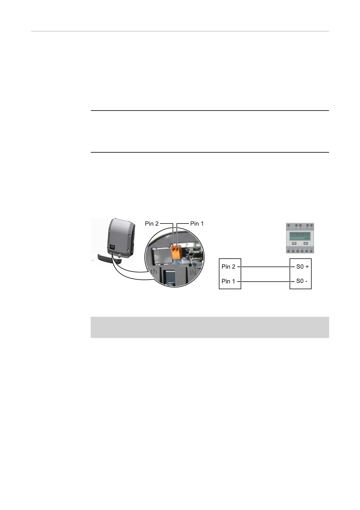
Wiring diagram variant 2: S0 meter
A meter for recording the self-consumption of each S0 can be connected dir-
ectly to the inverter. This S0 meter can be positioned directly at the feed-in point
or in the consumption branch.
IMPORTANT! In order to connect an S0 meter to the inverter, it may be neces-
sary to update the inverter firmware.
The S0 meter must comply with the IEC62053-31 Class B standard
Recommended max. pulse rate of the S0 meter:
PV output kWp [kW] Max. pulse rate per kWp
30 1000
20 2000
10 5000
≤ 5.5 10000
With this meter, dynamic power reduction can be performed in two ways:
-
Dynamic power reduction by means of inverter
For more information see chapter Dynamic power reduction by means of in-
verter on page 23
-
Dynamic power reduction by means of the Fronius Datamanager 2.0
for more info see: manuals.fronius.com/html/4204260191/
#0_m_0000017472
22

 Loading...