When designing cable cross-sections, take local regulations into account.
Connection conditions:
1
Carefully clean the oxide layer from the bare end of the cable by scraping it,
e.g. with a knife
IMPORTANT! Do not use brushes, files or emery paper, as the aluminium
particles get trapped and can be transferred to other conductors.
2
Once the oxide layer is removed, rub the end of the cable with a neutral
grease, such as non-acidic and non-alkaline Vaseline
3
Immediately connect the cable end to the terminal
IMPORTANT!Repeat the procedure if the cable has been disconnected and is to
be re-connected.
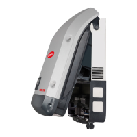
AC terminals
M32 (Ø 18-25 mm) mounted
M32 (Ø 7-15mm) enclosed
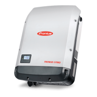
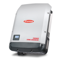
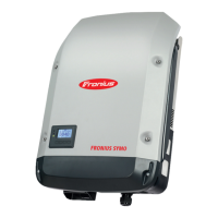
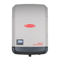
Fronius Symo Advanced
PE Ground conductor / earthing
L1-L3 Phase conductor
N Neutral conductor
Max. cross-section of each conductor
cable:
16 mm²
Min. cross-section of each conductor
cable:
in accordance with the fuse rating on
the AC side, but at least 2.5 mm²
The AC cables can be connected to
the AC terminals without ferrules.
M32 (Ø 18-25 mm) mounted
M32 (Ø 7-15 mm) enclosed
IMPORTANT! When using ferrules for AC cables with a cross-section of 16 mm²,
the ferrules must be crimped with a right-angled cross-section.
The use of ferrules with insulating collars is only permitted up to a max. cable
cross-section of 10 mm².
For a power category of 15-17.5 kW, an M32 PG gland is fitted (ø 18-25 mm) and
an M32 PG gland (ø 7-15 mm) supplied.
Cross section of
the AC cable
When using an M32 metric screw joint (reducer removed):
Cable diameter 11 - 21 mm
(with a cable diameter of 11 mm the strain-relief force is reduced from 100 N to
a maximum of 80 N)
With cable diameters greater than 21 mm, the M32 screw joint must be replaced
by an M32 screw joint with a larger clamping area - item number: 42,0407,0780 –
strain-relief device M32x1.5 clamping area 18–25.
46
 Loading...
