3
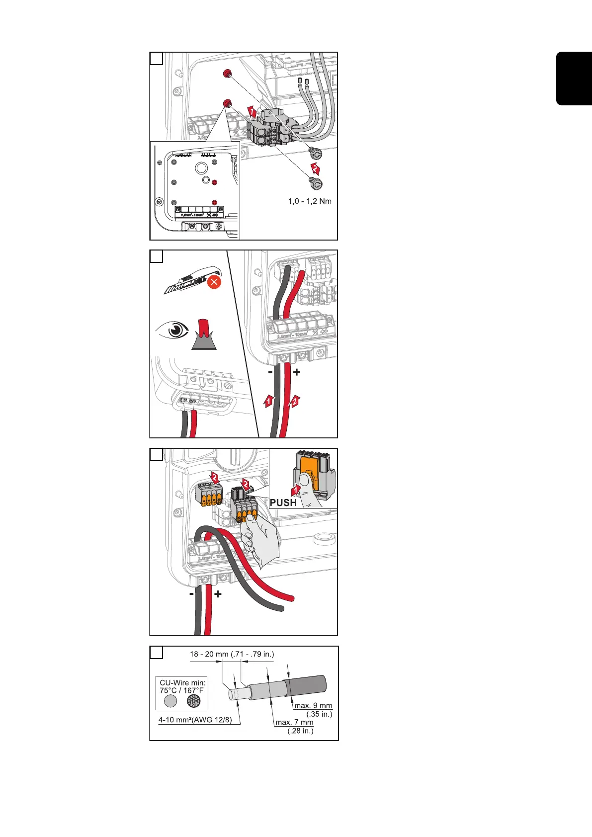
Insert the DC Connector GEN24 into
the inverter and secure with the two
screws (TX20) supplied at a torque of
1.0 ‑ 1.2 Nm.
4
Manually push the DC cables through
the DC bushings.
5
Press the lock on the back of the ter-
minal and remove the DC terminals.
6
Strip the insulation of the single con-
ductors by 18 - 20 mm.
Select the cable cross section in ac-
cordance with the instructions in Per-
missible cables for the electrical con-
nection from page 49.
133
EN

 Loading...


